



Before approving an electronics enclosure, test the assembled product with its intended cover, mounting, airflow and workload. Record temperatures over the operating cycle, compare each measurement with the requirement for that location, and keep unresolved conditions visible in the approval decision.
For a founder commissioning custom hardware, the useful deliverable is a reproducible thermal test record. A successful demonstration does not show how the same assembly behaves during sustained operation or at the intended ambient conditions. This guide explains what to ask the engineering team to define before the enclosure is accepted for its next development stage.
MakersGround’s historical مشروع Gomicron documents work across mechanical design, custom PCB electronics and firmware/control. That combination makes the enclosure and its operating electronics a relevant joint review. The project record does not establish a particular thermal test method or measured thermal performance; the plan below is general engineering guidance.
This is a development validation workflow. Product-specific safety and compliance assessment still requires the applicable requirements and appropriately qualified personnel. It does not establish one temperature that is safe for every product.
Define the approval decision first
Write down what this prototype must prove. Is the team approving the enclosure geometry for another iteration, releasing a pilot build or freezing a production design? Those decisions require different evidence.
For an early prototype, a useful objective might be: demonstrate that the assembled product completes its intended operating cycle, within specified temperature limits, in its intended mounting arrangement. List outstanding tests separately so that a limited development approval does not become an accidental production release.
Create a limits register before testing. Identify each relevant component, material or accessible surface; its applicable requirement; the source of that requirement; and the temperature location to which it applies. Assign responsibility for confirming product-specific safety and compliance requirements. Include the team’s chosen design margins and measurement uncertainty in the approval discussion, rather than inventing a universal pass temperature.
Describe the enclosure the test actually represents
Use the intended lid, fasteners, cable routing, mounting hardware and internal arrangement wherever practical. Record deviations, including substitute materials or an unfinished thermal interface. A convenient laboratory arrangement should not silently become the reference product.
Prepare a configuration sheet with:
- Enclosure, PCB and assembly revision identifiers
- Material and manufacturing process of the tested housing
- Vent openings, fan configuration and installed filters, if present
- Mounting orientation and clearance around the product
- Cable entry details and nearby equipment
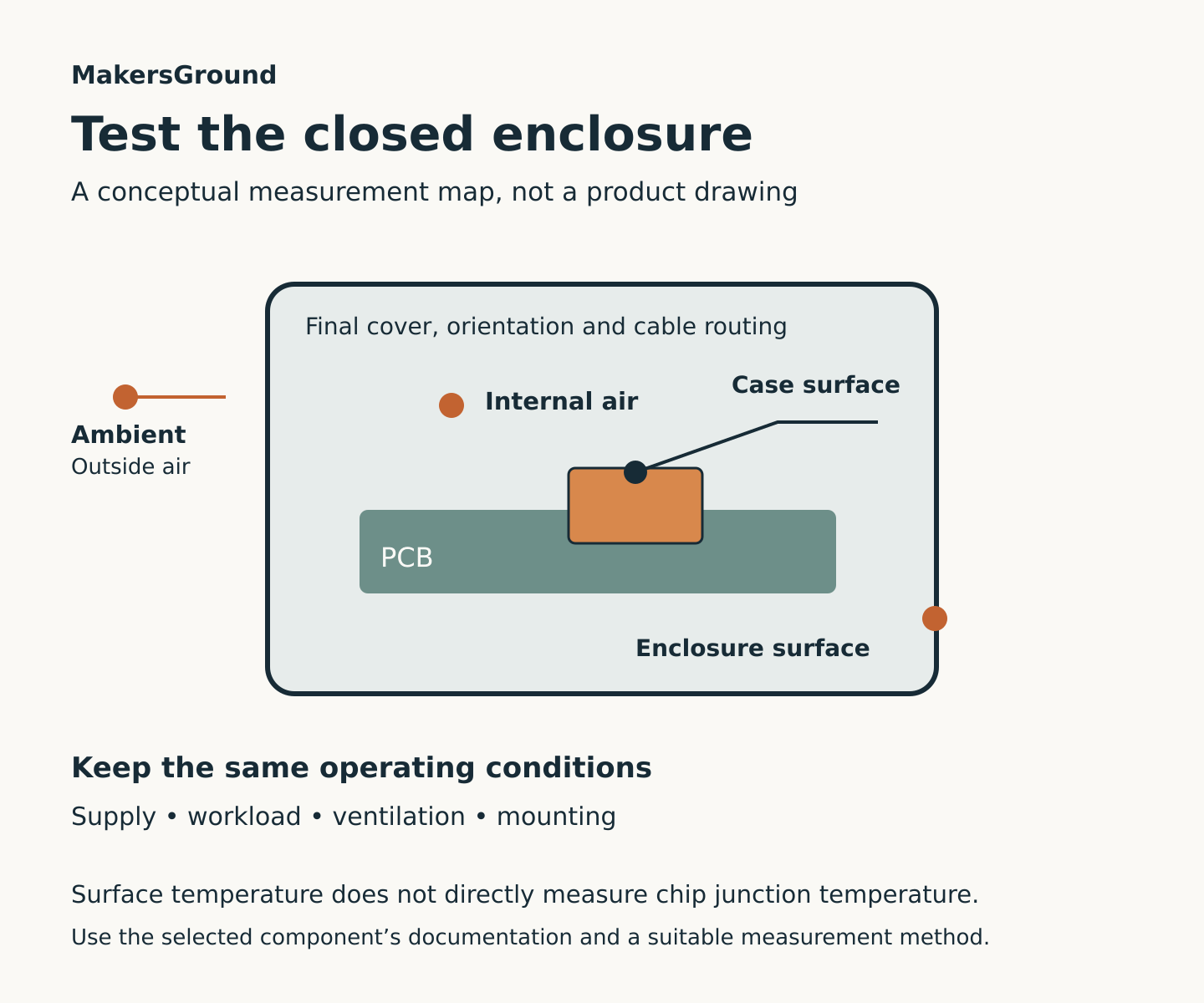
- Ambient target, measurement locations and operating profile
Treat an open-lid run as a diagnostic comparison. It can help identify a packaging issue, but it does not replace a closed-product run. Likewise, a printed fit-check housing should be recorded as such if production will use a different material or construction.
Keep temperature locations separate
External ambient air, air inside the enclosure, a component’s surface and its semiconductor junction are different quantities. Texas Instruments explains that even “ambient” depends on where it is measured. Its package guidance also cautions that junction-to-ambient thermal resistance depends on the board and surrounding conditions; a datasheet value is not a ready-made model of a custom enclosure. TI thermal metrics
Give every measurement channel an unambiguous name. For example: external reference air, internal air near the upper wall, regulator package top, connector body and accessible housing surface. Photograph the locations. Coordinate probe access with the PCB test-access plan so that the instrumentation can be connected in the intended assembly state.
Where a junction-temperature estimate is needed, document the manufacturer’s applicable estimation method and its assumptions. Label the result as an estimate. Do not relabel a camera’s surface reading as a measured junction temperature.
Test the workload, not just the idle state
Prepare an operating script that represents the product’s intended use. Include startup, sustained activity, repeated cycles and the relevant combinations of simultaneous loads. Record the software revision and settings that determine activity, because a thermal result without its workload is difficult to reproduce.
For intermittent operation, specify both the active period and the recovery period. Average power alone does not describe every transient temperature peak. Analog Devices discusses why predicting pulsed IC heating requires transient thermal information in addition to steady-state analysis. Analog Devices transient thermal analysis
Select credible demanding operating cases from the product requirements. Avoid substituting an arbitrary stress test without explaining what it represents. If an operating condition is outside the intended specification, identify it as a separate exploratory test and establish appropriate controls before running it.
Make airflow an explicit condition
If the design depends on moving air, record how that air is produced and where it travels. Note fan settings, restrictions and the installed geometry. TI’s airflow training addresses the effect of airflow on thermal performance and the measurement of safe-operating-area curves. For enclosure validation, the practical implication is to describe the cooling arrangement more precisely than “fan running.” TI airflow and thermal testing
For a passively cooled product, document orientation, surrounding clearances and any laboratory drafts. When using a chamber, consider whether its circulating air represents the intended installation. Keep installation assumptions visible in the report so that later teams do not apply the result to a different arrangement without review.
Choose measurements that preserve the setup
Use a thermal image to investigate surface patterns, then choose suitable measurement points for repeatable logging. Reflective surfaces need care: Fluke explains that an infrared image combines emitted and reflected radiation, and low-emissivity surfaces can make accurate temperature measurement difficult. Instrument settings and surface preparation therefore belong in the test record. Fluke on reflective surfaces
Contact probes also influence measurements. TI’s package guidance discusses local cooling caused by thermocouple wires and the importance of attachment and routing. Follow suitable component and instrument guidance instead of assuming that any taped probe gives an equivalent reading. TI thermal metrics
Route instrumentation so that the enclosure can close as intended. Record any measurement opening or altered seal. If instrumentation materially changes the assembly, explain the limitation rather than presenting the run as fully representative.
Record the heating curve
Log temperatures against time alongside operating state and relevant electrical measurements. Keep startup behavior, cycle peaks and recovery visible rather than saving only a final number.
TI’s thermal implementation guide describes thermal lag and equilibrium: a probe location can continue warming after load is applied, then level off as incoming and outgoing heat balance. Its example timing belongs to that particular setup, not every enclosure. TI thermal implementation guide
Define a stabilization criterion for the actual test before interpreting the result. For a repeating workload, look for a repeatable cycle envelope as well as peak temperatures. If a run ends while temperatures are still climbing, report it as incomplete for steady-state approval.
A hypothetical review example
Imagine a controller whose open-board demonstration looks acceptable. Inside its proposed housing, a repeated operating cycle produces progressively higher peaks near one power component. The team has not yet established a stable thermal cycle.
A useful next step is a controlled comparison: hold workload, ambient and instrumentation constant while changing one enclosure feature. That could be the component-to-wall thermal path or the mounting arrangement. Re-run the original profile, then evaluate the candidate against the same requirements. This example is illustrative; it is not a reported MakersGround or Gomicron test result.
Approve the evidence, not the impression
The review package should contain the tested configuration, limits register, operating script, measurement map, time-series results, uncertainties and unresolved deviations. State exactly what is approved and which changes require another review. Tie the results to the assembly and firmware revisions using a prototype revision record. A changed vent, thermal interface, power component or operating profile needs an explicit assessment of whether the earlier evidence still applies.
The practical goal is straightforward: make the thermal behavior understandable enough that the next design decision rests on evidence someone else can reproduce.
المصادر
Technical sources checked 16 October 2026. Manufacturer examples apply to their stated devices and conditions; the configuration and approval checklists are original engineering recommendations.
- Texas Instruments Semiconductor and IC Package Thermal Metrics SPRA953D, revised March 2024.
- Analog Devices Use Thermal Analysis to Predict an IC’s Transient Behavior and Avoid Overheating, February 2010.
- Texas Instruments Airflow and SOA training page, May 2018. The official page summary supports the airflow statement; the video was not independently reviewed in full.
- Fluke Understanding and fixing infrared thermography issues on reflective surfaces.
- Texas Instruments Thermal Implementation Guide for In-Package Magnetic Current Sensors SBOA400, July 2020.