


A housing can show a 0.50 mm clearance in CAD and still miss its assembly requirement when every component is within its drawing limits. The missing check is the dimensional chain between the two surfaces that define the gap.
Before ordering a prototype assembly, a tolerance stack-up helps answer a practical question: how much clearance remains when the contributing dimensions vary? It also shows which dimensions deserve closer control and which can stay relatively loose.
When separate suppliers make the housing, spacer and internal parts, they need a shared assembly requirement to review before fabrication. A clear section view, a short dimensional chain and an inspection plan can expose a problem that a nominal CAD assembly leaves hidden.
Define the gap and its acceptable range
Start with the two functional surfaces. Name the direction of measurement and the assembly condition: cover seated, cartridge against its stop, fasteners installed, or mechanism at a specified position. “Check the clearance” is too vague if different people can measure different gaps.
Then record the allowable range. A minimum gap may be needed to prevent contact. A maximum may matter for movement, alignment or a neighboring interface. The limits must come from the product’s requirements. A positive gap alone does not establish that the assembly works.
Keep three numbers separate:
- Nominal dimension: the value used to define the intended geometry.
- Part limits: the smallest and largest permitted values for each contributing dimension.
- Assembly limits: the acceptable range for the resulting gap.
Worst-case analysis combines part limits to find the extreme assembly values within the model. It does not estimate how often those combinations occur. PTC’s explanation of tolerance stack-up methods makes this distinction explicit.
Follow the surfaces that locate the parts
Draw a section through the gap and trace a continuous dimensional chain. Follow the shoulders, seats and contact faces that actually locate each component. A convenient CAD origin may have no physical equivalent during assembly or inspection.
Choose a functional reference that the design and inspection method can reproduce. A datum plane is an ideal reference established from a physical datum feature; the real surface can have form variation. KEYENCE’s datum examples illustrate that distinction. For a simple axial check, the base shoulder supporting the stack may be the useful starting reference.
Give every dimension a sign: does increasing it open the gap or consume it? Include only the dimensions on that chain. If the distance to a cover’s inner face is already controlled directly, adding the cover thickness again would double-count it.
Flag unresolved inputs rather than entering zero. Ask whether the dimensions describe finished surfaces, whether a coating sits in the contact path, and whether a spacer is supplied to a stated tolerance. An unknown contribution is a question for the drawing or supplier review.
A hypothetical axial-clearance example
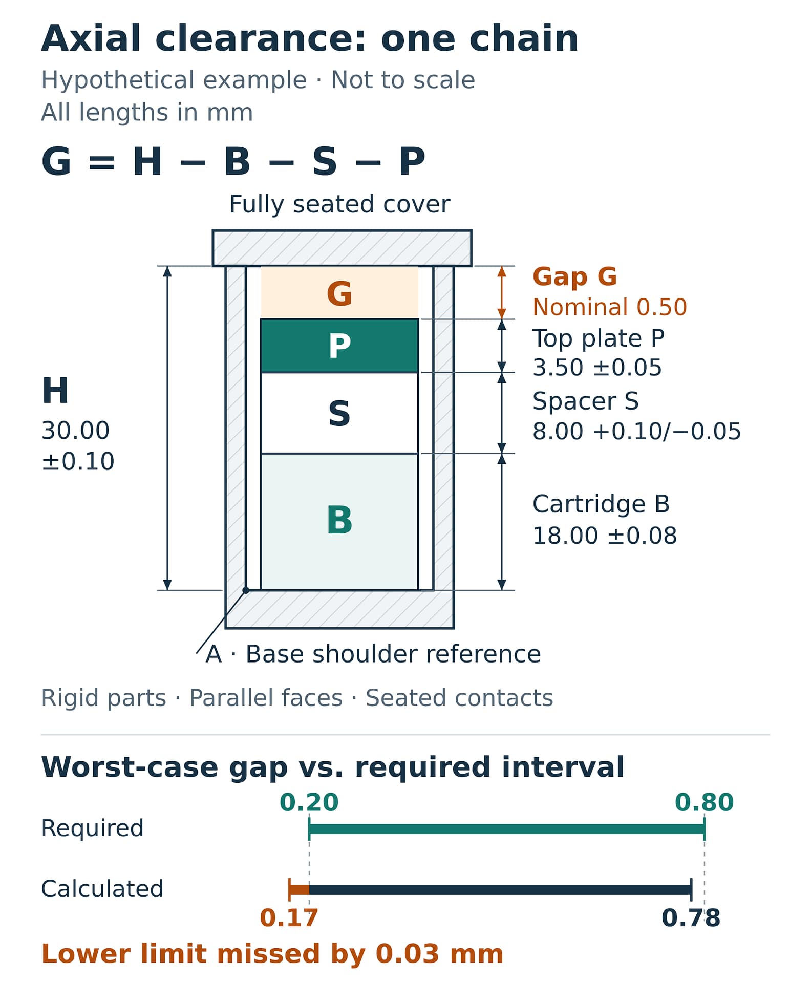
Consider a stationary cartridge, spacer and top plate stacked against a housing’s base shoulder, reference A. The cover seats on the housing independently of that stack. The gap G is measured from the top plate to the cover’s inner face.
This teaching example assumes rigid parts, parallel faces and complete seating along one axis. All dimensions and the required gap are hypothetical, in millimeters:
- H, base shoulder to seated cover inner face: 30.00 ±0.10, giving limits of 29.90 to 30.10.
- B, cartridge height: 18.00 ±0.08, giving limits of 17.92 to 18.08.
- S, spacer height: 8.00 +0.10/-0.05, giving limits of 7.95 to 8.10.
- P, top-plate thickness: 3.50 ±0.05, giving limits of 3.45 to 3.55.
- Required gap G: 0.20 to 0.80.
Calculate both ends of the interval
The signed chain is G = H – B – S – P.
At nominal dimensions, G = 30.00 – 18.00 – 8.00 – 3.50 = 0.50 mm, comfortably inside the required range.
For the minimum gap, use the smallest permitted base-to-cover dimension H and the largest internal stack:
G minimum = 29.90 – 18.08 – 8.10 – 3.55 = 0.17 mm.
For the maximum gap, use the largest permitted H and the smallest internal stack:
G maximum = 30.10 – 17.92 – 7.95 – 3.45 = 0.78 mm.
The minimum misses the 0.20 mm requirement by 0.03 mm. The asymmetric spacer tolerance also means the gap interval is not centered on its nominal value. Converting every input to explicit lower and upper limits keeps that detail visible.
Compare a nominal change with a tolerance change
Reducing the spacer nominal to 7.90 mm, with the same +0.10/-0.05 tolerance, moves the gap interval to 0.27 to 0.88 mm. It fixes the minimum but fails the maximum. In fact, the original interval is 0.61 mm wide and the permitted band is only 0.60 mm wide. A nominal shift alone cannot fit the whole interval inside it.
Keeping the spacer at 8.00 mm and changing its tolerance to ±0.03 mm produces a gap interval of 0.24 to 0.76 mm. That satisfies this simplified calculation, with 0.04 mm margin at each end. Whether it is a sensible design change depends on how the spacer will be made and measured.
Choose the analysis method deliberately
For an early prototype with little process data, the worst-case calculation is a useful starting point. It exposes permitted combinations that miss the requirement without assuming a production distribution.
Statistical analysis asks a different question: what distribution of assembly results follows from the distributions of the contributing dimensions? Root-sum-square, or RSS, is one approach. Sigmetrix describes the distinction between limits and statistical variation, including assumptions behind conventional RSS analysis.
A drawing tolerance is not automatically a measured standard deviation. Using tolerance half-widths in an RSS calculation requires a justified relationship between those limits and process variation. Distribution shape, centering and dependence between dimensions also matter. Shared process effects can make dimensions vary together, so they cannot simply be assumed independent. NIST’s propagation guidance explains why covariance can change a combined variation estimate.
Do not replace a failing worst-case result with a smaller RSS number just to release the drawing. First establish the process evidence, the acceptable assembly risk and the assumptions the team is willing to use.
Ask the supplier about the controlling dimensions
The example identifies the spacer as one possible place to recover margin. Send the supplier the functional section and identify the dimensions that consume the gap budget.
For this one-to-one chain, the full tolerance widths add to 0.61 mm: H contributes 0.20 mm, B 0.16 mm, S 0.15 mm and P 0.10 mm. Compare these contributions with the cost of controlling each feature before choosing a change.
Ask whether the proposed limits are achievable with the selected material, process, finish and quantity. Clarify whether inspection happens before or after finishing and whether additional operations or inspection time are needed. A different locating arrangement or fewer components in the chain may be worth comparing with a tighter part tolerance.
Separate a supplier’s quoted capability from evidence about the actual process. NIST describes process capability as a comparison between a stable process and specification limits. One prototype that fits is useful assembly evidence, but it does not establish the distribution of later parts.
Plan how the first parts will be checked
For each controlling dimension, write down the measurement reference, method and part condition. For the example, H must be checked with the cover seated on its intended housing stops. Measuring an external enclosure height would answer a different question.
Check the contributing dimensions and the assembled gap where accessible. If they disagree with the predicted chain, investigate the seating condition and model before changing a nominal dimension. Record burr removal, extra shims or hand fitting; otherwise the apparent success may depend on work absent from the next build instructions.
Measurement uncertainty also matters near an acceptance limit. NIST’s dimensional-calibration guidance explains that a measurement is an estimate with uncertainty. Select an inspection method that can support the decision, and agree how borderline results will be handled. A digital readout with several decimal places is insufficient evidence on its own.
Review the geometry beyond one axis
A passing axial chain leaves other questions open: can the parts tilt, do the locating holes align, and can surface form or assembly load change the local gap? Angular and nonparallel contributions do not necessarily affect clearance in a one-to-one ratio, as Sigmetrix explains in its stack-up overview.
Use the simple calculation to identify what needs a deeper geometric review. Where relevant, extend the model to geometric tolerances, contact behavior, deformation or operating temperature rather than treating the one-dimensional result as proof of the complete assembly.
Keep fit decisions connected to product development
مشروعنا مشروع Gomicron brought together mechanical design, PCB electronics, firmware and control, slicing software, prototyping and manufacturing. In an integrated product, changing a locating surface can affect sensor placement, cable clearance or assembly access. Review those interfaces whenever a fit change moves a neighboring part.
For teams using our hardware, robotics and product-development services, the useful handoff is a reviewable fit requirement alongside the design files. It gives the mechanical, fabrication and assembly teams a specific result to check.
Before releasing the prototype parts
- Name the gap, its two defining surfaces and the assembly condition.
- Set the required minimum and maximum from the product’s needs.
- Trace the signed dimensional chain from a reproducible reference.
- Record every lower and upper limit, including asymmetric tolerances.
- Calculate both extremes and compare them with both assembly limits.
- Review unresolved geometry, finishing and seating contributions.
- Confirm manufacturing and inspection plans for the controlling dimensions.
- Measure the first build and record any fitting or adjustment it required.
The release decision should leave the team with a clear answer: which combinations of permitted dimensions work, what margin remains, and which assumptions the first build still needs to test.
Technical sources and linked project information checked on October 19, 2026 and rechecked on November 5, 2026.