


A credible battery runtime estimate starts with the current drawn by the complete device over a representative operating cycle. Measure sleeping, sensing, processing, communicating and recovery activity at the battery input, then relate that demand to usable battery capacity under the intended conditions. A processor’s sleep specification or a battery’s headline capacity cannot answer the runtime question alone.
For a connected prototype, the practical decision is whether its enclosure, power circuit and firmware can deliver the required service interval together. The following method produces an auditable estimate and a test plan before anyone turns that estimate into a product promise.
Define the service the battery must support
Write the operating requirement before selecting a capacity. “Runs for three months” needs a measurement interval, reporting frequency, communication conditions and a clear endpoint. Does the device stop when its supply reaches a defined voltage, when a reset occurs, or when it can no longer deliver a valid measurement?
- Specify the normal workload: sensor rate, processing, radio activity, indicators and user interactions.
- Define the supported environment and battery condition at installation.
- Include expected maintenance, startup, reconnection and update events.
- Set separate limits for average consumption and correct operation during the largest current pulse.
Keep measurement availability in the requirement. Extending sleep is not an improvement if the product then misses the event it was designed to capture.
Measure at one clearly defined boundary
Prefer a measurement of the complete board at its battery input for the first system budget. Label that boundary in the schematic and test record. It should include the regulators, sensors and other loads that the battery actually supplies. An isolated microcontroller rail answers a different question.
If measurements are made on regulated output rails instead, convert their power demand to battery demand using the relevant input voltage and conversion efficiency. Do not simply add currents from rails at different voltages. Equally, do not add regulator losses a second time when the recorded current already comes from the battery input.
Texas Instruments explains why converter selection must consider the load profile and efficiency during both active and inactive periods. Peak efficiency at a large load does not describe operation while the device spends most of its time asleep. Check the selected regulator’s light-load behavior, quiescent current and shutdown conditions, rather than treating those terms as interchangeable. TI’s pulsed-load converter application report provides the underlying distinction.
Use the final peripheral configuration where possible. Record whether debug hardware, USB power, indicator LEDs or an external sensor supply are present. A test powered partly through another cable can omit demand from the battery measurement.
Capture a cycle, then inspect the events inside it
The measuring instrument must resolve low idle current without clipping the larger pulses. Check range, sampling behavior and the voltage disturbance introduced by the setup. Record the actual device supply voltage as well as current when a pulse could approach the system’s operating limit.
Nordic’s hardware verification guidance calls out measurement sensitivity, dynamic range and sample rate, and asks designers to check supply transients during transmission. Its nRF9161 examples are device-specific, not universal current figures for other radios. Read the verification guidance.
A current trace with firmware event markers is useful because it links a burst to work such as sensor warmup, packet delivery or retry. Nordic’s Power Profiler Kit II documentation, for example, describes low-current and short-peak measurements with digital inputs for code correlation. This is an example of the capability to look for, not a claim about MakersGround’s equipment or a recommendation for every voltage and load.
Capture enough complete cycles to expose variation. Then run separate cases for startup, a missing connection, repeated user input and maintenance. Do not hide rare activity inside an unexplained allowance: record how often it is assumed to occur.
A hypothetical one-minute sensing cycle
The following numbers are invented to demonstrate the calculation. They are not measurements from a MakersGround product. Assume the currents are measured at the battery input and remain constant within each listed state.
- Sleep: 0.10 mA for 58 seconds, consuming 5.8 mA·s.
- Sense and process: 8 mA for 1.5 seconds, consuming 12 mA·s.
- Transmit: 40 mA for 0.5 seconds, consuming 20 mA·s.
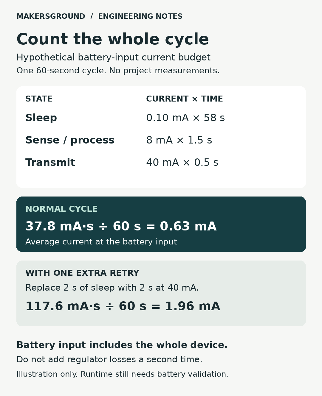
The durations total 60 seconds. Total charge per cycle is 37.8 mA·s, so average current is 37.8 ÷ 60 = 0.63 mA. For a varying trace, integrate current over the cycle rather than replacing every burst with its peak value.
Now assume, solely for this example, that testing has established 1,200 mAh of usable capacity under the relevant conditions. Dividing 1,200 mAh by 0.63 mA gives approximately 1,905 hours, or 79 days. This is a simplified charge-budget result, not validated calendar runtime. It leaves out effects such as storage loss and changes in demand during discharge unless those are already represented in the assumptions.
One retry changes the result
Suppose every cycle includes an additional two-second transmission at 40 mA, replacing two seconds of sleep. The added charge is (40 − 0.10) × 2 = 79.8 mA·s. The revised cycle consumes 117.6 mA·s and averages 1.96 mA. Under the same simplified capacity assumption, the result falls to about 25.5 days.
The engineering question is now specific: can the expected communication environment sustain the original duty cycle, and what retry limit preserves useful operation? A firmware change that reduces retries may matter more than a small improvement in the sleeping processor alone. The example does not establish what retry policy any real product should use.
Use capacity that belongs to the test conditions
Capacity is not an unconditional number. Energizer defines rated capacity in relation to a specified load, temperature and cutoff voltage. Its definition of cutoff also includes the point below which equipment will not operate or operation is not recommended. See Energizer’s battery glossary.
Obtain the selected cell’s discharge information and match it to the product’s load and endpoint. Energizer’s alkaline handbook illustrates how temperature, discharge rate, internal resistance and cutoff affect accessible service. Those curves describe alkaline batteries; do not transfer their numerical values to a rechargeable lithium pack or a coin cell. See the alkaline handbook.
Repeat the current budget at representative battery voltages; a regulated load can draw a different input current as the battery discharges. Repeat system checks near the intended end of discharge. A device may meet an average-current budget but still reset during a transmission pulse. Define the permitted voltage range from the actual components and battery guidance. Do not lower a battery’s specified cutoff or defeat its protection to meet a runtime target.
Make the prototype review reproducible
Attach a compact evidence record to the hardware revision:
- Configuration: board revision, firmware version, peripherals, radio settings and battery specification.
- Conditions: supply voltage, temperature, communication environment and workload.
- Measurement: instrument, range, capture duration, connection diagram and raw trace.
- Results: charge per cycle, average current, peak current, minimum supply voltage and successful task completion.
- Exceptions: startup, retry and maintenance costs, with their assumed frequency.
- Decision: required service interval, evidence still missing and the next test that could change acceptance.
Compare revisions under the same conditions. Keep a changed reporting interval visible rather than presenting it as an unexplained hardware efficiency gain. Before release, run representative complete-device discharge tests; the spreadsheet is a planning tool, not a substitute for that evidence.
Connect the budget to hardware and firmware decisions
يوثّق Smart Glasses project record documents MakersGround’s device design, hardware and software work around a connected camera wearable. It does not publish a battery specification or runtime validation result. Its relevance here is the integration boundary: peripherals, communications and software behavior belong in the same engineering conversation.
For a new device, bring that boundary into the hardware and firmware development scope early. The useful output is a traceable budget: what the device does, what each cycle costs, which battery conditions support it and what has been tested. That makes the next decision concrete, whether it is changing a regulator, shortening a sensor warmup, revising a retry policy or selecting a different capacity.
المصادر
Technical sources opened and checked on November 3, 2026. Manufacturer examples support the principles identified above; they are not MakersGround test results.
- Texas Instruments: Selecting a DC/DC Converter for Maximum Battery Life in Pulsed-Load Applications, SLVA740A.
- Nordic Semiconductor: nRF9161 hardware verification, power consumption.
- Nordic Semiconductor: Power Profiler Kit II.
- Energizer: Battery glossary and FAQs.
- Energizer: Alkaline Manganese Dioxide Handbook and Application Manual.