


An I2C recovery test should prove more than a successful transaction after a fault. It should show that recovery finishes within an agreed bound, the peripheral has the intended configuration, and the application resumes with valid new data. If those conditions cannot be established, the product needs an explicit fault state rather than an endless retry loop.
For a founder reviewing an embedded prototype, the useful question is: what evidence shows that the product is trustworthy again? This guide sets out a validation plan for a single-controller I2C bus on a development bench. It is not a universal recovery implementation or permission to inject faults into operating equipment.
يوثّق مشروع Gomicron الهندسي documents work across custom electronics, firmware and control, alongside mechanical and product software development. That is the relevant company context for reviewing hardware and firmware together. The public project record does not establish that Gomicron used I2C or the recovery methods discussed here.
Define recovery at the application boundary
Begin with a short acceptance contract. Name the affected function, the information it supplies, the longest interruption the application can tolerate, and the response when that limit is exceeded. Derive the limits from the actual device documentation and product requirements. Do not borrow a timeout from an unrelated board.
For a monitoring function, the contract might require the application to mark its reading unavailable during recovery and retain the age of the last valid sample. A stored value can remain useful for diagnosis without being presented as a current measurement. The return to normal operation should depend on an explicit validity check, not simply the absence of another driver error.
Record who owns each part of that contract: electronics for reset and power domains, firmware for recovery sequencing, and the application for data validity and user-visible status. Our IoT and robotics engineering services provide the broader electronics and firmware context; this article concentrates on validating one bus fault path.
Separate fault classes before choosing a response
A missing acknowledgment, a transfer timeout and a line held low are different observations. Preserve the most specific status the hardware and driver can provide. As an implementation example, the Linux I2C fault-code documentation distinguishes an address phase without acknowledgment from a timed-out operation; it also distinguishes arbitration loss. These names are Linux conventions, not a requirement to use Linux or a guarantee that every controller exposes the same detail.
For each test, capture both the software report and the observed bus state. A generic “sensor error” may be sufficient for an operator but is usually too vague for an engineering acceptance record. Keep the address, operation, transfer stage where observable, elapsed time and recovery action in diagnostic evidence.
Do not treat nine clocks as a universal reset
NXP’s I2C specification, revision 7.0, section 3.1.16, distinguishes two stuck-line cases. When SDA is stuck low, it describes sending nine clock pulses and escalating to hardware reset or a power cycle if the target does not release it. When SCL is stuck low, its preferred approach is hardware reset where available, or a power cycle. A controller cannot assume it can clock a line that remains held low.
That distinction is a starting point for design review, not a complete sequence for every board. Check the controller, target devices, any bus buffers, and their datasheets. Account for permitted clock stretching, startup conditions, pin modes, and reset or power domains. A shared reset must not silently reset another function that the application expects to remain available.
Recovery can also affect peripheral state. The Linux I2C fault-injection guide warns that an interrupted write can leave a device ready to accept data when further clocks arrive. It recommends checking the hardware setup and verifying recovery with an oscilloscope or logic analyzer. Do not assume that a released bus proves registers remained unchanged.
Build a controlled fault test matrix
Use a dedicated development setup with a reviewed injection fixture. Agree the electrical limits and isolate hazardous outputs before testing. Do not hard-short signals or drive against another output to create a fault. Review the fixture and connections with the responsible electronics engineer, and preserve the board and firmware revisions used for every result.
Target absent or temporarily unavailable
Use a supported test arrangement to make the target unavailable. Check that the diagnostic record identifies the failed operation, retries remain within the agreed budget, and the application reports unavailable data. Restoring availability should trigger the defined initialization and validation path, not an unrecorded assumption that the old configuration survived.
Interrupted transfer and held data line
Exercise a controlled interrupted transfer where the test architecture supports it. Then test a persistent held-low condition separately. These are different acceptance cases: a recoverable interruption may clear, while a persistent fault should terminate the recovery attempt and leave the application in its defined degraded state. Record the waveform and software events together so the result can be reproduced.
Held clock line
Check the response to an unresponsive clock line using the approved fixture. The acceptance condition is not “nine pulses were requested.” It is that the product recognizes the failure, follows its permitted reset or escalation path, and stops within its recovery budget if the fault remains. Verify that unrelated functions remain within their own requirements.
Peripheral reset and repeated faults
Where supported, reset the peripheral while the controller continues running. Verify configuration restoration and the first valid post-reset measurement. Repeat faults at different transfer stages and near the recovery deadline. Check for accumulating retry counts, abandoned locks or resources, and misleading healthy status after the budget is exhausted.
A hypothetical environmental monitor
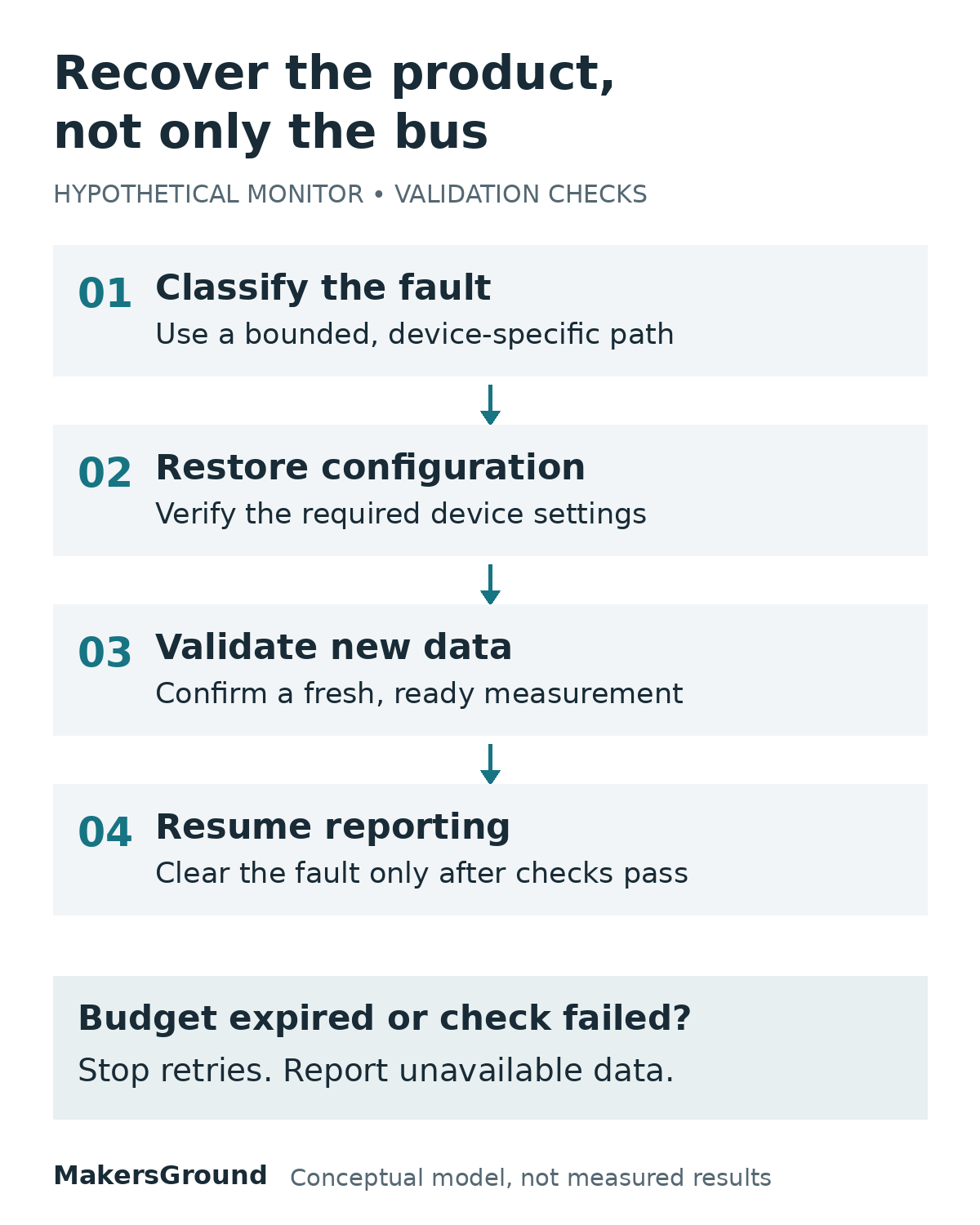
Consider a hypothetical, non-safety environmental monitor with one controller and an I2C sensor. This example is not a MakersGround customer deployment. After an interrupted transaction, the application marks the measurement unavailable and records when its last valid sample was obtained.
The firmware classifies the fault and follows the device-specific recovery path within a finite attempt and time budget. If communication returns, it establishes the expected configuration, using readback where the device supports it. It then waits for the device’s documented measurement-ready condition and checks a new sample before clearing the fault status.
If any required check fails, the monitor remains visibly unavailable. It does not keep presenting the cached number as live data. The actual deadlines, configuration checks and measurement-ready mechanism would be specified for the selected sensor and application, not supplied by this illustration.
Keep evidence that supports the release decision
Each result should connect the injected condition to the product outcome. Keep a compact test record containing:
- Board, firmware, driver and peripheral identifiers, plus the relevant configuration.
- Fault method, transfer stage, fixture settings and repeat count.
- Observed SDA and SCL behavior, aligned with diagnostic timestamps.
- Recovery duration and attempts, compared with the agreed acceptance bounds.
- Evidence of restored configuration and a valid new sample, or the explicit fault state when recovery was not possible.
- Effects on other functions, unresolved limitations and the person responsible for the next decision.
A pass applies to the tested conditions. It does not establish that every electrical disturbance, peripheral variant or operating state is covered. Keep those boundaries visible when approving the next prototype or pilot stage.
Ask for a recovery demonstration that ends with evidence
Before accepting the implementation, ask the team to demonstrate one recoverable interruption and one persistent fault. In the first case, follow the evidence from the bus trace to restored configuration and valid application data. In the second, show that retries stop and the product reports the failure clearly.
That gives the review a concrete endpoint: either the product has met its recovery contract, or the remaining fault is visible and bounded. A successful bus transaction alone is not that endpoint.
المصادر
Primary technical sources and the public project record were checked on 21 October 2026. The NXP document is revision 7.0 dated 1 October 2021. The validation checklist and monitor scenario are original engineering recommendations and a hypothetical example, not reported test results.
- NXP UM10204 I2C-bus specification and user manual, especially section 3.1.16.
- Linux kernel I2C and SMBus fault codes.
- Linux kernel I2C fault injection.
- MakersGround Gomicron project record, historical engineering scope only.