



After changing a hardware prototype, prepare a matched set of design and build records, identify what was actually assembled, and connect the revised unit to its test results. The useful question is not simply “Did we update the CAD?” It is “Can someone build and check this revision without guessing which files, parts and software belong together?” Record what changed, what remains applicable and what evidence the next build must produce.
This checklist follows one hypothetical connector relocation through that process. It is intended for product founders and engineering teams preparing another prototype or handing a revised design to a build partner.
1. Identify the unit tested, not a folder called latest
A mechanical model, PCB layout and firmware release can each have a different revision. An assembled prototype can contain a mixture of those revisions, plus rework that exists only on that unit. Give the physical unit an identifier and record its actual configuration before using its results to make a design decision.
A compact record might list the enclosure revision, board revision, applicable parts list, firmware identifier and configuration. Keep the design proposed for the next build separate from the unit already tested. “Latest” does not tell another person which combination produced an observation.
NASA’s configuration-management guidance connects identified baselines, evaluated changes, configuration history and verification. For a small prototype team, those principles can become a short change record and build manifest; the documentation should match the project’s complexity.
2. Separate the observed problem from the proposed fix
Write down the observation before naming the solution. Include the unit, conditions and evidence: what could not be assembled, what measurement differed, or which behavior did not match the requirement. Then state the proposed change and why it might address that problem.
“Move J1” is an instruction. “The mating plug cannot be fully seated with the enclosure fitted; move J1 and verify access on the next assembled unit” connects an observation, a hypothesis and an acceptance check. A drawing change does not demonstrate that the hypothesis worked.
Identify the affected interfaces and who can approve a substitution or deviation. If someone proposes a different connector while building, the decision should be traceable to that proposal rather than disappearing into an informal conversation.
3. Worked example: moving connector J1 on board revision B
This is a hypothetical example, not a documented MakersGround project change. Prototype units P01 and P02 use board revision A. A team proposes moving connector J1 for better enclosure access on board revision B, while keeping the same connector part and net assignments. New unit P03 will evaluate the change. No dimensions or successful result are assumed.
| Record | Revision decision | Evidence needed |
|---|---|---|
| Mechanical CAD and drawings | Check J1’s new position against the opening, mating plug, cable space and assembly access. Update affected geometry or dimensions. | Identified CAD and drawing revisions, followed by the relevant fit and access checks on P03. |
| PCB sources and outputs | Move the footprint and review affected routing. Generate the accepted fabrication and assembly outputs from board revision B. | Source revision and output manifest, with agreed units and coordinate origin. |
| Parts list and assembly instructions | The BOM can remain applicable if the actual parts are unchanged. Update instructions where position, orientation or assembly sequence changes. | Applicable BOM revision and clear J1 orientation; record any substitute separately. |
| Firmware and configuration | A position change with unchanged electrical connections does not automatically require new firmware. Assess pin mapping and other affected assumptions. | Exact applicable software and configuration identifiers, with the reason for keeping or changing them. |
| Physical build record | Preserve P01 and P02 records. Identify P03’s actual construction, parts and any rework. | P03’s as-built configuration; distinguish a reworked A board from a newly fabricated B board. |
| Verification record | Select checks for the affected mechanical, electrical and assembly interfaces. | Procedure, conditions, observations and decision tied to P03; unresolved issues remain visible. |
The table links a design decision to evidence. A reviewed layout or successful export is evidence about the files; it does not prove that the revised physical assembly works.
4. Generate a consistent release pack
Before sending files, identify the source revisions and generate the agreed outputs from them. List the files included, their revision or identifier, and their purpose. Confirm the build partner’s accepted formats, units and coordinate origin. A prototype does not need every possible manufacturing document, but required items should not be inferred from filenames.
The KiCad 9.0 PCB Editor documentation illustrates the distinction between fabrication plots, drill files and component-placement files. These outputs serve different purposes. It is a versioned tool example, not a claim about MakersGround’s software or a universal requirement to use one export format.
If the team uses Git, a release tag can identify a point in source history. Record the commit identifier too: tags can be deleted. A source commit is distinct from the actual firmware bytes installed; recording the binary’s checksum helps identify those bytes, but does not establish functional correctness.
5. Record the intended build and the as-built unit separately
The released pack describes the intended configuration. The build record describes what was actually assembled. Record deviations, substitutions and rework against the unit, including the decision that accepted them or the question still awaiting resolution.
Suppose P03 is assembled using an A board with a connector rework. That may help investigate access, but it is not the same construction as a newly fabricated B board. Label the experiment accordingly. Neither the new CAD filename nor an updated label should erase that distinction.
Keep superseded releases retrievable for the units that used them, while clearly identifying the pack intended for the next build. Historical records should explain an old result without allowing obsolete files to be mistaken for current instructions.
6. Retest the affected interfaces against explicit checks
Choose retesting from the change’s impact, rather than copying an old “passed” result. For the J1 example, relevant questions could include whether the intended plug can be seated, whether the cable and assembly access remain acceptable, and whether affected connections and device behavior still meet their requirements.
Define the procedure, conditions and acceptance criteria before claiming success. Record the exact unit and configuration used, the observed result, and the decision it supports. A fit check on a reworked board answers a narrower question than checking the newly fabricated assembly.
Tests and safe handling depend on the actual electronics and product; this checklist does not prescribe universal powered-test steps. If the change affects pin mapping, timing or command behavior, revisit the hardware–firmware interface agreement as well as the build records.
7. What the historical Gomicron material can show
The Gomicron engineering project documents MakersGround’s work across mechanical design, PCB and electronics, firmware and control, slicing software, prototyping and manufacturing. The original project material provides concrete design context for work spanning these disciplines.
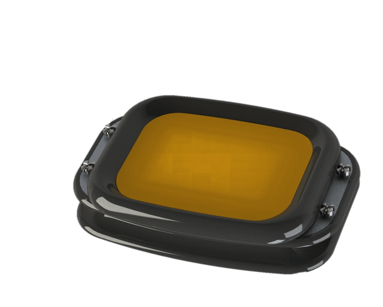
This historical render shows mechanical-design context. It is not a manufacturing drawing, measured fit result or published revision history. The checklist here is a proposed approach, rather than a claim about the release process used on Gomicron.
8. Ask five questions before the next prototype build
- Which issue and physical unit motivated the change?
- Which design, output, parts and software records changed, and which remain applicable?
- Can the build partner identify the intended pack and the decisions needed for substitutions?
- How will the actual assembly and any deviations be recorded?
- Which checks on which unit will support the next decision?
For a team in Lebanon, the Gulf or elsewhere in MENA, settle file formats, units and document language with the actual build partner. Make approval responsibilities clear when design and assembly happen in different places.
Explore hardware product development and electronics and PCB development, or discuss the next prototype build with MakersGround. Bring the observed issue, current files and unit records so the review starts from the configuration you have.
By Sawsan Sayad. Technical references and linked project evidence checked on 5 October 2026. The connector example is hypothetical.