



Before integrating a connected device, agree a versioned interface specification covering electrical limits, data meaning, timing, command outcomes, recovery and access. For each boundary, name an owner on both sides and a test that proves the agreement. A connector pinout or message format alone is not enough.
This checklist is for founders and engineering teams coordinating electronics, embedded firmware and application development. It helps turn “these parts should work together” into decisions that can be reviewed before a PCB revision or integrated prototype.
What belongs in an interface specification?
An interface is the boundary where one part of the system supplies something another part depends on: power, a signal, a measurement, a command or a software response. Write down both sides of that boundary. A sensor may report a value correctly while an application interprets it with the wrong units or treats an old reading as current.
NASA’s interface management guidance connects interface control with integration and verification. Its interface requirements outline includes responsibilities, engineering units, tolerances and interface requirements. The checklist below is an original, smaller-scale application of those ideas for connected products.
- Boundary: which two components exchange power, information or commands?
- Owners: who maintains each side, and who approves a change?
- Meaning: what does each signal or value represent, including units and invalid states?
- Behaviour: what happens at startup, during operation, after a timeout and after recovery?
- Evidence: which inspection, measurement or integration test will establish that the agreed behaviour occurs?
1. Resolve the physical and electrical boundary first
For a board-to-board or sensor connection, record the connector orientation and pin numbering, signal direction, power requirements, logic levels, reference ground and permitted operating limits. Identify which component provides any required pull-up or termination. Check the selected components’ actual datasheets and bus documentation; a familiar connector does not establish electrical compatibility.
Agree what the pins do before firmware has initialized. Ask what happens if one board is powered while the other is off, if the sensor disconnects, or if reset occurs while a transaction is underway. The answers should be explicit design requirements with a test owner, rather than assumptions left for the first integrated build.
For a product containing moving mechanisms, also identify the coordinate reference, travel limits and responsibility for protective functions. A communication agreement is one part of engineering the system; it does not establish that the machine is safe to operate.
2. Define the meaning of data before choosing its format
For every measurement, specify its name, unit, sign convention, expected range, resolution, validity indicator and sampling rule. Distinguish the time of measurement from the time a gateway or server receives it. Decide how the receiver knows a reading is stale and what it should display when no valid reading is available.
Keep “zero,” “unknown” and “sensor fault” separate where they mean different things. Record where calibration or unit conversion happens so two layers do not apply the same conversion twice. Agree limits on packet size, strings and identifiers before committing to firmware memory allocation.
If using JSON, IETF RFC 8259 describes interoperability issues including duplicate object names and numeric precision. Use unique field names and numerical representations both implementations can support. Successful parsing establishes that a message has an accepted form; it does not establish that its measurement is current or correct.
3. Separate a received command from a completed action
A response saying “received” answers a different question from “accepted,” “applied” or “failed.” Define the states the application can show and what evidence triggers each transition. Include a request identifier so a delayed response can be matched to the command that caused it.
Specify who owns timeout decisions, whether a command may be retried, and how duplicates are handled. Repeating “set the sampling interval to 60 seconds” can be designed to leave the same configuration in place. Repeating “add one unit” changes state again. Those operations need different retry rules.
After a lost connection, the application may not know whether a command took effect. Provide a way to query the device’s actual configuration or command outcome rather than treating a timeout as proof that nothing happened.
A worked example: configuring a sensor’s sampling interval
Hypothetical example: an environmental monitoring device accepts an application request to change its sampling interval. The values and behaviours below are illustrative design choices, not a MakersGround deployment or a description of Gomicron’s firmware.
| Contract item | Illustrative agreement | Acceptance check |
|---|---|---|
| Interval and units | An integer number of seconds, from 10 to 3,600 inclusive. | Reject 0, 9, 3,601 and fractional values; accept the two boundaries. |
| Request identifier | Each new request has an identifier. Retries reuse that identifier and the same payload. | A retry produces the same recorded outcome. Reusing the identifier with a different interval is rejected. |
| Command outcome | Report accepted, applied, rejected or failed. Applied means the new interval is durably stored and the sampling task uses it. | Check the matching outcome and active configuration. Observe timestamped samples at the agreed interval and project-specific timing tolerance. |
| Persistence | The applied interval survives restart. A repeated request must not change its meaning. | Restart after application and verify the interval. Test retry behaviour across restart explicitly. |
| Unknown outcome | If the response is lost, query active configuration. Do not display success based only on a sent request. | Drop a response after application and verify the application resolves the state correctly. |
The table still needs project-specific decisions: response deadlines, how long request outcomes are retained, who may configure the device, and what happens if persistence fails. Put those decisions in the same specification. Then run the tests with both implementations connected; a simulator alone cannot verify the electrical boundary.
4. Include recovery, access and version changes
Write separate expectations for loss of connectivity, firmware restart and loss of power. Define which settings persist, how invalid state is detected, and how the device reports that it is ready. If readings are buffered, agree their ordering and whether they retain their original measurement time when sent later.
List who can read, configure and update the device, including local service interfaces. NIST’s IoT Device Cybersecurity Capability Core Baseline provides a starting point for device cybersecurity requirements, including interface access and software updates. Apply requirements to the actual product and its operating environment; citing the baseline is not a certification or evidence of a security assessment.
Record hardware revision, firmware version and interface version separately. Keep a compatibility table for the combinations that have actually been tested. Agree how old receivers handle new optional fields and how incompatible changes are detected. A changed unit under an unchanged field name can break meaning even when the message still parses.
What the Gomicron project can show
MakersGround’s Gomicron 3D printer engineering record documents work across mechanical design, custom PCB electronics, firmware, slicing software, prototyping and manufacturing. Original CAD, hardware photographs and software screenshots make those disciplines visible.
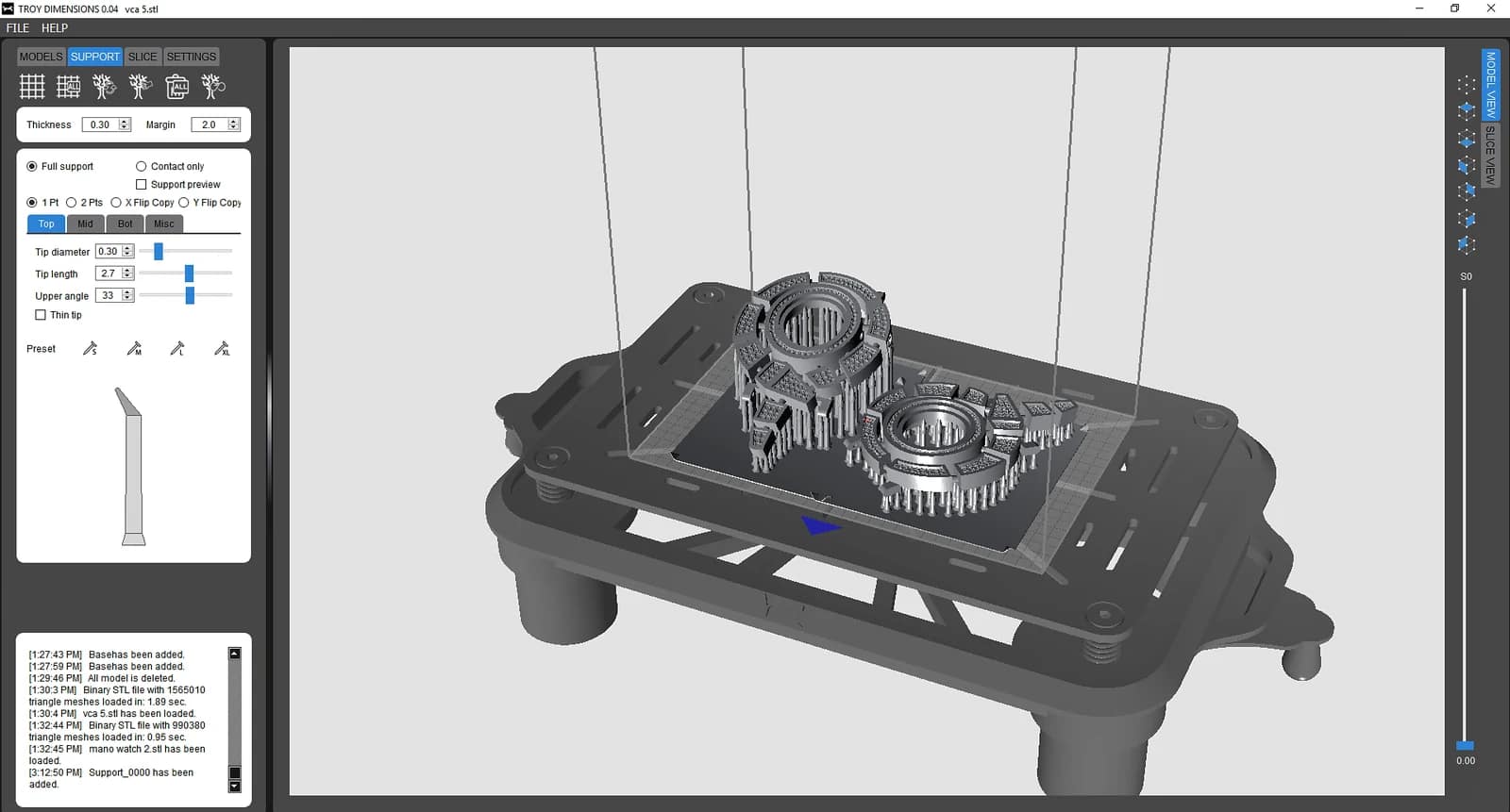
These materials illustrate the scope of a product spanning physical hardware and software. They do not disclose its interface specification, communication protocol, test results or current commercial status. The checklist and sensor example above are general engineering guidance, not a claim that this exact process or protocol was used on that project.
What should you bring to an interface review?
Bring the current schematic and connector definitions, component datasheets, a list of messages and commands, example payloads, startup and recovery expectations, and the hardware/firmware revisions being integrated. Mark unresolved decisions and assign owners. For a deployment in Lebanon, the Gulf or elsewhere in MENA, document the actual site’s connectivity, operator languages, service access and support responsibilities rather than assuming a common regional operating environment.
Finish the review with a versioned specification, named owners on both sides and a short acceptance test list. If you need help defining the boundary between a board, firmware and an application, explore MakersGround’s embedded systems and firmware services and electronics and PCB development, or discuss your existing design and integration questions.
By Sawsan Sayad. Technical references and linked project evidence checked on 3 October 2026. The worked example is hypothetical.