



Before sending a prototype PCB for fabrication, decide how the assembled board will be powered, measured, programmed and diagnosed. Give each important test a reachable connection, a suitable reference and a documented expected result. A test point is useful only when someone can connect the intended instrument without changing the fault they are investigating.
For a founder commissioning custom hardware, the practical deliverable is a test-access plan alongside the schematic and layout. It should show what the team can learn from the first assembled boards, including when the application firmware does not start. This article explains what belongs in that plan and which decisions depend on the actual components and instruments.
Why test access belongs in the mechanical review
A pad that looks accessible in a PCB editor may sit beneath a display, battery holder or mounting bracket in the assembled product. A connector may fit while its cable cannot bend far enough to clear the enclosure. Check access in the assembly state in which the test will actually happen, rather than assuming that every investigation takes place on a bare board.
MakersGround’s published Gomicron project record documents MakersGround’s mechanical design, PCB electronics and firmware/control contribution. It provides a concrete reason to consider these disciplines together. It does not document Gomicron’s particular test pads, debug connector or bring-up procedure. The recommendations below are general engineering guidance, not a reconstruction of that project’s testing history.
Ask the mechanical and electronics teams to review the proposed probe, connector and cable together. Include clearance for fingers or fixture movement, not just the nominal contact point. Mark any measurement that requires a cover to be removed, and distinguish a development-only opening from a planned service connection.
Start with questions, then choose the connections
Do not begin by adding a pad to every net. Write the questions that would stop the first board from progressing, then identify the evidence needed to answer them. This produces a smaller, more purposeful access plan.
| Question | Access to consider | What to record |
|---|---|---|
| Is the intended supply reaching the circuit? | Input and relevant regulated rails, with suitable reference points | Rail name, permitted range and operating state |
| Can the processor be programmed and identified? | The selected device’s supported debug or programming interface | Pin mapping, voltage reference, tool and connection method |
| Is reset behaving as designed? | Reset observation and, where supported, controlled reset access | Expected polarity, timing and conditions |
| Where does communication stop? | Selected observable boundaries on the relevant bus | Signal names, electrical levels and expected transaction |
| Can the board be tested when the main application fails? | A documented recovery path and limited diagnostic output | Recovery prerequisites and information that may be erased |
The table is a planning framework, not a universal pin list. A high impedance analog node, an RF path and a slow digital status line need different treatment. Adding a long branch to reach a convenient pad can alter the circuit. Review proposed access with the signal’s layout requirements rather than applying one footprint everywhere.
Separate power, programming and diagnostic access
Power access answers a specific measurement question
Name the rail and the reference beside each planned measurement. Identify whether the check is performed with the board unpowered, during startup or under a defined load. Do not copy another board’s current limit or rail values: derive them from the actual design and the relevant component documentation.
Texas Instruments’ TM4C12x JTAG application report illustrates why a failed debugger connection is not automatically a software problem. Its device-specific troubleshooting sequence checks supply rails, the debug header, voltage reference and reset. Those categories are useful prompts for a review; its numerical values and recovery instructions apply to the stated device family, not every microcontroller.
A programming connector needs more than a familiar shape
Confirm the exact pinout at both ends of the cable, the supported signal levels and the role of each connection. A voltage-reference pin is not automatically a supply output. In TI’s XDS Target Connection Guide, target connection requirements depend on both the device and debug probe. Routing, termination and optional signals must be checked against the chosen combination.
Document which source powers the target during programming. If USB, a bench supply and a debugger can be attached at the same time, have the designer review the allowed combinations and any risk of unintended power paths. The technician should not have to infer that policy from connector labels.
Diagnostic access should survive a broken application
A status LED can show activity but rarely explains which initialization step failed. Decide which limited diagnostic output would distinguish the failures you expect to investigate. That might be a boot status, a reset reason or a communication error code, depending on the product. These are design choices, not capabilities that every controller provides automatically.
Keep the recovery procedure separate from a routine firmware update. Record whether recovery requires physical access, a particular boot state or an erase operation. Do not assume that restoring connectivity preserves stored data. Development access also needs a later production and service policy; leaving every debug function available is not a substitute for deciding who may use it.
Design the measurement connection as well as the pad
The instrument becomes part of the circuit while it is connected. Tektronix explains that probe resistance and capacitance can load the measured node and change the observed signal in its guide to probe effects. A pad alone therefore does not establish that a waveform will be trustworthy.
For a proposed waveform measurement, note the intended probe type, its loading and the reference connection. Tektronix’s probe-loading guidance also explains the effect of ground-lead inductance. A nearby reference connection can allow a shorter return path, but the appropriate arrangement still depends on the instrument, signal and circuit.
Keep this article’s example within low-voltage prototype work. Do not connect a grounded oscilloscope probe to an arbitrary point in a mains-connected or otherwise hazardous circuit. Such measurements require appropriately rated equipment, a reviewed method and qualified personnel. Never remove protective earth to make a measurement work.
A hypothetical board that powers up but will not communicate
Consider a hypothetical low-voltage controller with a regulated supply, a processor and an external peripheral. The board powers on, but the intended peripheral transaction never completes. This is an illustrative design review, not a MakersGround project result.
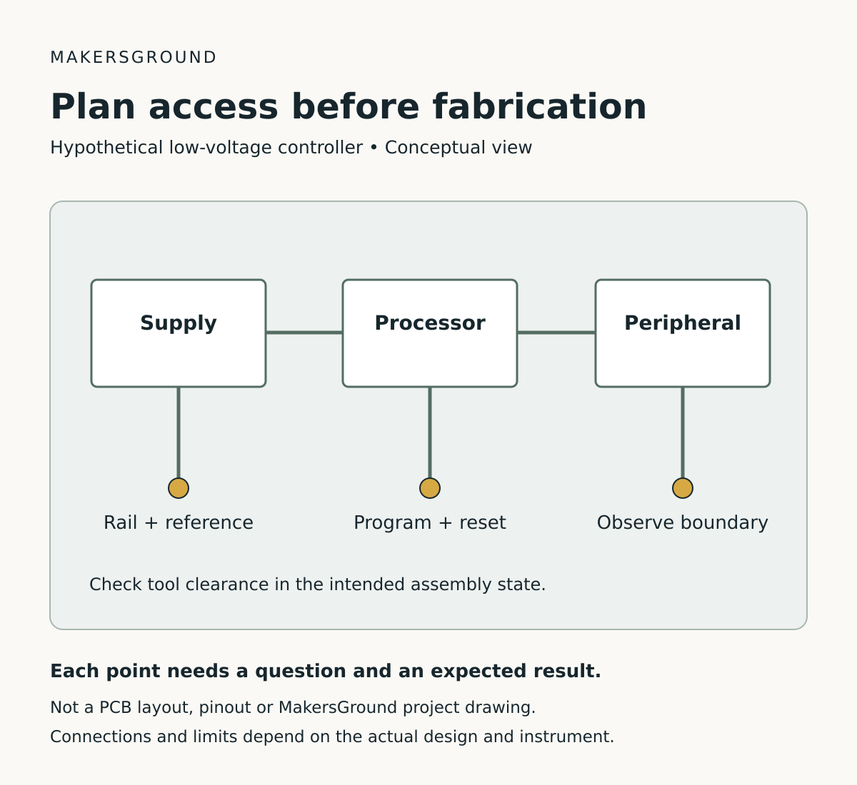
Without a plan, the team might repeatedly change firmware because the board’s power LED is lit. With planned access, they can first check the relevant rail, confirm processor identification through the supported programming interface, and observe the communication boundary. Each result narrows the investigation without proving more than it measures.
A rail within its static limit does not prove that it remains stable during a transaction. A connected debugger does not prove that the application has initialized the peripheral. Activity at the processor pin does not prove that the same signal arrives correctly at the peripheral. Put access where it helps separate those questions, and record the operating state with each observation.
The associated diagram is a conceptual access map. It deliberately contains no component values, pin numbers or routing dimensions. Those belong in the reviewed design files for the actual board.
Review the first-board plan before fabrication
- Every priority question has a named observation or test, not merely a pad label.
- Each connection is reachable in the intended assembly state with the actual tool or proposed fixture.
- Programming pinout, signal levels, reference and power-source combinations are documented.
- Probe loading, return path and sensitive-net routing have been considered.
- Expected results refer to the schematic revision, component documentation and operating state.
- Recovery prerequisites and possible data loss are explicit.
- Development access and eventual production/service access are separate decisions.
Keep the plan short enough to use at the bench. One annotated board view, a connection table and a test sequence may be more useful than a long document that cannot be matched to the assembled unit. Connect the plan to the actual board and firmware revision using the records described in our prototype revision checklist.
What a buyer should ask to receive
When commissioning custom electronics and embedded development, ask for a test-access review before the first PCB order. Request the access map, supported programming connection, expected observations and a list of tests that cannot be performed in the assembled state. The important outcome is a clear answer to “How will we isolate a fault on the first board?”
This does not replace functional testing, safety evaluation or production test development. It makes the prototype easier to investigate while the design is still being learned. A successful bring-up should leave a record of what was checked and what remains uncertain, rather than just a board that happened to run once.
Sources
Technical sources checked 11 October 2026. Manufacturer examples are limited to their stated devices and instruments.
- Texas Instruments: Using TM4C12x Devices Over JTAG Interface, SPMA075, particularly the connection and troubleshooting sections.
- Texas Instruments: XDS Target Connection Guide.
- Tektronix: How Oscilloscope Probes Affect Your Measurement.
- Tektronix: How to Minimize Probe Loading with Low Capacitance Probes.