


Before building a hardware prototype, define the cable harness as part of the assembly: which points it connects, where it runs, how it is supported, what moves and how someone will install or replace it. Review that route with the intended enclosure and mating connectors. A complete pinout can still leave a cable trapped under a cover or a latch impossible to reach.
When commissioning custom electronics or a small machine, include a harness drawing and a documented fit and service-access review in the prototype scope. Agree which enclosure, connectors and cable parts that review will represent. The question is practical: can someone install and disconnect the intended connections in the available space?
MakersGround’s Gomicron engineering project documents work across mechanical design, PCB electronics, firmware and control, slicing software, prototyping and manufacturing. A harness review brings a concrete assembly question to that multidisciplinary scope: do the connector locations, cable route and service sequence work together?
Start with a connection map and an installation state
Give each harness and branch an identifier. Record its endpoints, the connector orientation and the exact mating parts. Include contacts, housings, seals or accessories where applicable, rather than specifying only a familiar connector-family name. A drawing should make clear whether a connector is shown from the mating face or the wire-entry side.
Keep the electrical requirements beside that map: circuit function, expected load, wire requirements and operating conditions. Check the selected component documentation. For example, Molex’s Mini-Fit Jr BMI HPC product specification makes current rating dependent on the application and identifies loading, temperature and surrounding construction as relevant conditions. There is no universal connector current rating. Check the exact contact, wire and connector configuration and the conditions attached to its rating.
Then define the assembly state being reviewed. Is the board already fixed to the base? Is the lid attached? Must a cable pass through an opening before its connector is fitted? These questions determine the installation sequence. Record a temporary prototype arrangement explicitly if it will differ from the next build.
Put the cable route into the mechanical review
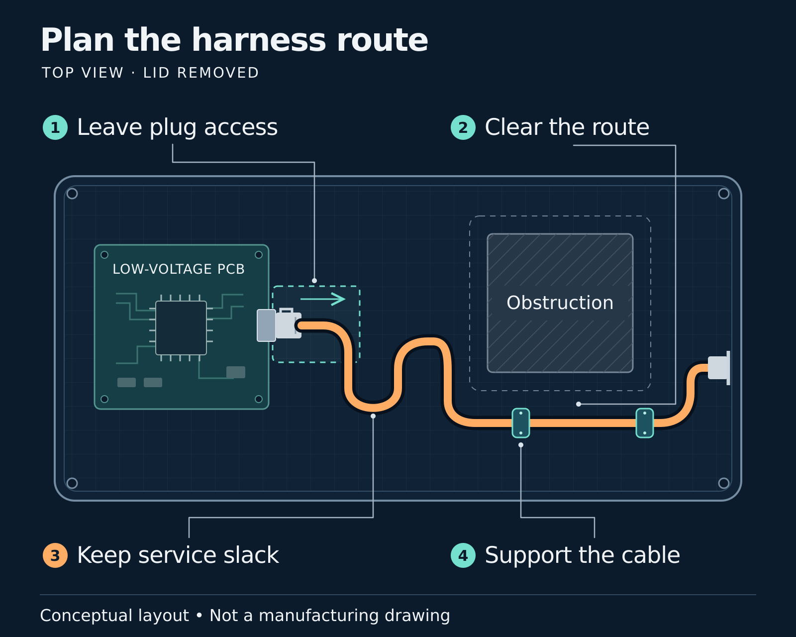
Reserve space for the cable and its supports in the assembly model or an annotated drawing. Show branch points, enclosure crossings, nearby fasteners, sharp edges and parts that will move or be removed. Use the intended cable diameter and connector envelope once those parts are selected.
NASA’s cable and harness workmanship standard treats routing, support, abrasion protection and access as explicit engineering concerns. It is a high-assurance reference, not a claim that an ordinary prototype follows NASA requirements. Its relevance here is that a harness needs a physical definition as well as an electrical one.
Check the route with the cover fitted and with the intended service part removed. Reserve space for fastener tools and hands where they are needed. A cable that fits after careful manipulation may still lack a repeatable installation path. Note where a protective sleeve, edge treatment or support is required, and specify the actual solution through the product’s design review.
Choose support locations so that normal cable handling does not turn the board connector into the assembly’s only restraint. Leave the wire exit and any manufacturer-specified free length undisturbed. More cable ties do not automatically improve the design: placement and tightness must suit the cable, connector and installation.
Separate fixed wiring from moving cable
Mark each section by its actual use. A cable fixed inside an enclosure, one disturbed occasionally during servicing and one flexed on every machine cycle face different requirements. A flexible-feeling cable is not evidence that it suits repeated motion.
igus distinguishes fixed, occasional-flex and continuous-carrier conditions in its bend-radius guidance. The applicable limit depends on the selected cable and conditions such as temperature and travel. There is no universal bend radius. Use the cable’s specification for the real installation, including the motion and temperature conditions.
If a cable moves during operation
Define the complete movement envelope, including travel extremes and intermediate positions. Identify bending, twisting and any change in support. Check the cable with the proposed carrier or guidance arrangement, not as a loose sample on a bench.
In its cable-carrier installation guidance, igus discusses clearance, separation, jacket interaction, freedom of movement and strain relief. Those details depend on the selected system. A carrier cannot be treated simply as an empty channel to fill tightly.
Specify the movement conditions and evidence required for the next development decision. Record the travel, motion frequency and configuration being evaluated. A brief motion demonstration may expose interference; it does not establish the cable’s service life. Use a reviewed test setup with qualified personnel and protective measures intact.
Make connector access and retention visible
Reserve room to insert the mating part, operate its latch and remove it by the intended method. Include the wire exit, any backshell and the bend that follows. Check access using the actual parts when possible; two connector bodies that mate in isolation may be difficult to join inside the enclosure.
Keep three questions separate:
- Are the contacts correctly retained inside their housings?
- Are the two connector halves fully mated and retained?
- Is the harness supported so external loads are handled as intended?
Molex’s Mini-Fit Jr application specification addresses terminal seating, locking and wire dress, including free wire length near the housing. For the connector actually selected, check the contact, wire and tooling as a compatible set and preserve the space its instructions require.
Define service slack by the task it enables. A removable panel may need enough controlled slack to reach its disconnect point. Extra loose wire also needs somewhere to sit when the panel is closed. Document both states, rather than asking the assembler to find a convenient place for the excess.
A hypothetical removable-panel problem
Consider a low-voltage prototype controller with a sensor mounted on a removable side panel. The electrical drawing correctly connects the sensor to the PCB. During the first fit check, the panel can be closed, but opening it pulls the cable tight before the connector latch becomes accessible.
The team now has a specific design question: how far must the panel move before the connector can be released? The review compares the required opening distance with the available cable movement, then considers a defined slack pocket, revised support locations or a different removal sequence. Each option must also fit when the panel is closed and respect the selected cable’s bending requirements.
For the next prototype, acceptance should include opening the panel by the intended procedure, reaching and releasing the connector, and closing the assembly without trapping the harness. Record the route and support arrangement used.
Prepare a build record another person can use
Keep the harness package proportional to the prototype. A short drawing set can be sufficient if it removes the important ambiguities. A useful starting package includes:
- A connection map with endpoint identifiers, pin references and viewing orientation
- A parts list identifying the selected wire, contacts, housings and accessories
- Lengths and branch locations, with defined measurement references and permitted variation
- A route sketch showing support, pass-throughs, service slack and keep-out areas
- The assembly sequence and connector-manufacturer instructions that apply
- A unit or harness identifier linking the actual build to inspection and test records
Record substitutions and rework against the actual assembly. A changed cable construction can require another routing or motion review even if the endpoints remain identical. Our prototype revision checklist explains how to keep those as-built changes connected to the design files and subsequent tests.
Agree what the prototype must prove
Review physical fit and electrical function separately. Before energizing a new assembly, use the project’s approved inspection and connection-verification procedure. The method and test limits must suit the actual circuit, attached electronics and components; do not borrow test voltages from an unrelated harness standard.
For the mechanical review, record whether the harness follows the defined route, the connectors can be fully engaged and released, the cover closes correctly, and the specified service operation is possible. For a moving section, record the tested travel and configuration, the observed behavior and any damage or interference. Preserve failures as well as successful checks.
End the review with a clear decision: which configuration is accepted for the next build, what remains unresolved and which changes require another check. An initial continuity result does not establish long-term flex durability, just as an attractive route photograph does not establish electrical correctness.
When discussing custom electronics and hardware development with MakersGround, bring the enclosure model, connection map, selected component documents and the service tasks the product must support. Include harness routing in the agreed deliverables before ordering the next prototype. That gives the mechanical and electronics work a shared, testable assembly target.
Sources
Technical sources and linked project evidence checked 18 October 2026. Manufacturer examples apply to their stated product families and conditions. The project link establishes Gomicron’s multidisciplinary scope; it does not document the harness practices discussed here. The checklist is an original planning recommendation and the panel example is hypothetical. Product-specific design and test procedures require their own engineering review.
- NASA-STD-8739.4A, Change 4, Change 4 issued 13 April 2022: routing, support, access and harness inspection records.
- igus: Cable bend radius, with installation-type distinctions.
- igus: Cable and hose packages, including carrier installation considerations.
- Molex 55560002-AS, Revision A1, dated 9 January 2025: Mini-Fit Jr application specification.
- Molex 437590001-PS, Revision A2, dated 24 October 2024: Mini-Fit Jr BMI HPC product specification.