


A quadrature encoder can make a position display look convincing while the conversion behind it is wrong. Before using that reading for control or acceptance, verify the number of counts per known shaft movement, the sign of the change and the behavior at the highest required speed. Keep the raw counter visible during those tests. A rounded angle or distance display can hide the fault you need to find.
For a prototype machine, the deliverable is a documented chain from physical movement to reported units. This guide covers incremental A/B feedback and count acquisition. It does not establish machine safety, replace the selected component documentation or prove the accuracy of the complete mechanism.
Write down what one count means
Start with the encoder datasheet rather than a number copied into firmware. Manufacturers do not always use CPR and PPR in the same way. Record the stated number of electrical cycles on one channel per encoder-shaft revolution, then record how the receiver decodes them. In x1 mode, one selected edge per cycle is counted; x2 counts two edges; x4 counts both edges of both A and B. US Digital explains these terminology and decoding distinctions.
Make a small configuration record before the first test:
- Encoder part number, output interface and datasheet revision.
- Channel cycles per encoder-shaft revolution, stated without an ambiguous acronym.
- Decoder mode, input polarity, counter range and any index-reset behavior.
- Where the encoder is mounted, and the ratio between that shaft and the reported movement.
- The physical direction defined as positive, including the viewpoint used to describe it.
Do not assume that the motor shaft, encoder shaft and output shaft make the same number of revolutions. A correct counter with the wrong transmission ratio still gives the wrong reported position.
Our historical Gomicron project documents mechanical design, custom electronics, firmware and control within one product. That combined scope is the context for this interface review. The public record does not establish a particular encoder, decoder or validation method used on Gomicron; the tests below are general recommendations.
Prove scale and direction before closing the loop
Begin with controlled, slow movement and an independent way to identify the displacement. Use an appropriate safe test arrangement, with drive torque disabled where the mechanism permits it. Do not hand-turn a hazardous or unsupported load. A qualified machine review must define safe access, restraint and the conditions for powered testing.
Record the starting count, move through a known encoder-shaft rotation, then record the ending count. Compare the change with the expected value before converting it to degrees or millimetres. Repeat in both directions. Keep the raw readings and the reference method, not just a photograph of a plausible display.
Check the sign against actual movement. A-leading-B is not a universal synonym for clockwise: the manufacturer’s viewpoint and wiring convention matter. For example, the Dynapar HS35R manual, revision S dated September 2013, specifies a viewing end and includes reverse phasing. Verify the selected encoder and configured decoder together. Do not discover a sign mismatch by enabling an unverified feedback loop.
Keep channel frequency separate from count rate
Consider a hypothetical encoder specified as 500 A-channel cycles per encoder-shaft revolution. With x4 decoding, one shaft revolution produces 2,000 counts. At 60 rpm, that is one revolution per second: 500 channel cycles per second and 2,000 count transitions per second. These are different quantities.
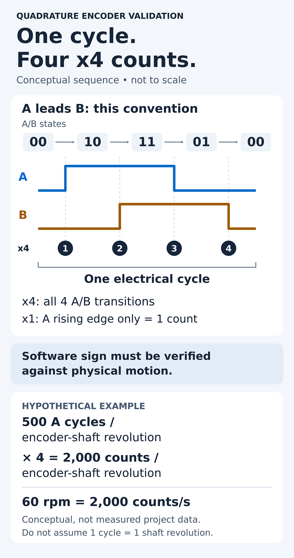
At a hypothetical 1,800 rpm, the same encoder produces 15,000 channel cycles per second and 60,000 count transitions per second. The calculation describes the requested signal rate, not the capability of an encoder, input circuit or processor. Confirm which quantity each manufacturer’s maximum-frequency specification describes.
Check the input voltage and electrical interface, minimum accepted pulse widths, phase and duty-cycle limits, and the receiver’s filtering configuration. A filter chosen to suppress short disturbances must still pass legitimate pulses at the intended speed. The Beckhoff EL5112 filter documentation illustrates why this is device-specific: limits depend on input mode, and the terminal exposes filter-violation counters. Its values are not settings to copy into another product.
Repeat the count check using the actual cable, connector, receiver and configured filter. Include representative switching loads and cable routing. A clean signal at the encoder connector does not establish what the controller receives at the other end of the harness.
Test the counter boundary deliberately
A raw counter has a finite range. Record its configured maximum and what happens at the boundary in each direction. The TI eQEP reference guide SPRU790D, revised December 2008, is a historical implementation example: its position counter can wrap from the configured maximum to zero and underflow in reverse. Check the current reference manual for the actual controller rather than assuming identical behavior.
For a hypothetical full-range 16-bit counter, a known forward movement from raw 65,530 to raw 6 crosses zero once and represents 12 counts, provided there are no additional full counter wraps. Ordinary subtraction of those displayed numbers would suggest a large negative change. Test both forward and reverse crossings, including how the application accumulates motion beyond one hardware-counter range.
Do not apply that example as a universal software recipe. A count difference becomes ambiguous if unobserved motion can span too much of the counter range between reads. Specify the allowed speed, longest read interval, configured modulus and direction assumptions. Test the implementation against those limits, including delayed processing and restart behavior.
Use the index as evidence, not a way to erase evidence
If the encoder provides an index channel, record what the controller does with it. An index event may latch a value, reset a counter or participate in a separate reference procedure, depending on the hardware and configuration. TI’s eQEP guide describes latching the position count at index events as a way to inspect accumulated counts.
Where supported, compare counts between equivalent index events during motion in one direction. Preserve the count and diagnostic state before any reset overwrites them. A display that returns to zero on every revolution can conceal the discrepancy that would otherwise identify a missed or extra count.
This is an additional consistency check, not a complete measurement reference. State which index edge and phase qualify the event, and use the selected component documentation. An absent index is not permission to invent one in the test record.
Separate count integrity from mechanical accuracy
Correct counts do not prove that the load reached the intended position. An encoder observes movement at its own mounting location. Coupling slip, backlash or compliance elsewhere in the mechanism can produce output error even when the counter acquires every valid transition. More counts also do not automatically remove systematic measurement error. Dynapar distinguishes resolution, accuracy and system repeatability.
Keep two acceptance questions separate: did the electronics and firmware acquire the expected count, and did the output mechanism move as required? Use a suitable independent physical measurement for the latter. Do not use the same encoder-derived display as both the result and its reference.
Leave a test record another engineer can repeat
Define the pass criteria before testing, including how the chosen reference’s uncertainty or edge alignment affects the comparison. Do not adjust the counts-per-unit constant merely to make one run agree. Investigate an incorrect scale, lost transitions and mechanical error separately.
- Establish the baseline. Record hardware and firmware revisions, encoder model, interface, cable and decoder settings. Confirm scale and sign with known slow movement.
- Exercise the operating envelope. Repeat the agreed motion in both directions at the required speeds, including starts, reversals and relevant electrical loads. Record expected and observed raw-count changes.
- Cross the boundaries. Test overflow, underflow, index handling where present, delayed reads and restart. Preserve diagnostic flags and counters where the selected hardware exposes them.
- Check the output separately. Compare actual mechanism movement with an independent reference. Record unresolved differences rather than hiding them in a calibration factor.
The acceptance package should identify the exact configuration, test conditions, reference method, observed counts, physical measurements and remaining gaps. For a custom machine engineering review, that is more useful than a smooth position display: it shows which part of the measurement chain has actually been demonstrated.
Sources and scope
Primary manufacturer documents and the public project record were checked on 31 October 2026. The workflow, numerical examples and conceptual diagram are original explanatory material, not measured MakersGround project results. Device-specific limits must be checked against the selected parts and configuration; the older TI guide is identified as a historical implementation example.
- US Digital: Resolution, Accuracy, and Precision of Encoders.
- Dynapar: HS35R installation manual.
- Beckhoff EL5112: Adjustable interference pulse filters.
- Texas Instruments: eQEP reference guide SPRU790D, revised December 2008.
- Dynapar: Encoder Resolution, Encoder Accuracy and System Repeatability.
- MakersGround: Gomicron DLP 3D Printer Engineering.