


A prototype exchanges a few messages on a short bench cable, then becomes unreliable when the intended harness and remaining nodes are connected. Before changing retries or rewriting the parser, check what reaches the receiving transceiver. Cable layout, termination, idle behavior and transmitter handover can each produce symptoms that resemble a protocol fault.
This guide covers bring-up of a low-voltage, half-duplex RS-485 prototype. The aim is to establish a documented electrical baseline before investigating application messages. It is a development review, not a complete installation, EMC or machine-safety assessment.
Separate the electrical link from the message rules
RS-485 specifies electrical characteristics for drivers and receivers. It does not select the message format, addressing scheme or retry policy. Two devices with RS-485 terminals are not necessarily interoperable. TI’s RS-485 design guide makes this electrical-layer scope explicit.
If the product uses Modbus RTU, review its serial settings, framing and timing against the Modbus serial-line specification separately. A clean differential waveform cannot prove that the address or register request is correct, while a decoded message cannot establish adequate electrical margin.
Start with one connection sheet: transceiver part numbers, supply ranges, connector pinouts, cable specification, node positions, baud rate and UART format. Trace connector labels back to the device truth tables rather than assuming that an A or B marking on an adapter establishes polarity throughout the system.
Draw the cable as a trunk with short branches
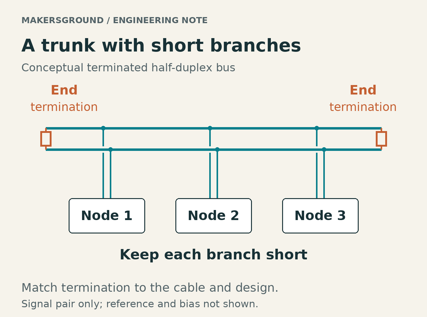
For the conventional multipoint arrangement, draw one main twisted-pair trunk and mark every branch between it and a transceiver. Include connector breakout wiring and internal harness lengths. A neat schematic can conceal a physical star with several long cables leaving one junction.
Keep branches short relative to the signal edge traveling along them. TI’s guide relates permissible stub length to driver rise time and cable propagation speed, so baud rate alone is an incomplete basis for choosing a branch length. A lower-rate UART connected to a fast-edge transceiver still needs a transmission-line review. TI design guide, sections 3 and 6.
Use the intended cable and connectors early. Record temporary adapters, extension leads and the position of any USB interface. Moving an adapter from a cable end to a branch changes the network being tested.
Put termination at the cable ends
For a conventionally terminated half-duplex trunk, place termination across the signal pair at its two physical ends. Intermediate nodes do not each receive another terminator. Check module jumpers and switch settings: an unnoticed resistor on every development board adds parallel loading.
Match the termination network to the cable’s differential characteristic impedance and account for the complete circuit. The familiar 120-ohm value belongs to a nominal 120-ohm cable system, not every cable that carries RS-485. Characteristic impedance describes traveling signals; it is not the conductor’s DC resistance measured with a multimeter. TI’s termination guidance.
A power-off resistance check can help find assembly mistakes. Two isolated 120-ohm resistors in parallel give 60 ohms, but connected bias networks and other circuit paths can change the reading. Compare with the actual schematic rather than using 60 ohms as a universal pass criterion.
Some deliberately short or slow links can operate without termination. TI describes conditions for that choice. Treat it as a documented design decision with waveform verification, not a conclusion drawn from one successful bench exchange.
Decide what the receiver sees during idle
Between transmissions, every driver may be disabled. The receiver must still produce a defined idle output. Check the exact transceiver’s failsafe behavior for an idle, open or shorted bus; those conditions should not be assumed equivalent across parts.
As a device-specific example, the TI THVD1450 datasheet specifies failsafe-high reception for open, shorted and idle terminated inputs. Its positive-going receiver threshold is between -100 mV and -20 mV under the stated operating conditions. That differs from assuming every receiver switches at a universal positive 200 mV threshold.
Where external idle bias is required, calculate it for the assembled network. Include minimum supply, resistor tolerances, receiver loading, both terminations and the required noise margin. Also check the load seen by an active driver. TI’s passive-failsafe analysis treats bias and termination together. Copying a resistor pair without its assumptions can compromise either idle margin or driven operation.
Document which node supplies external bias and check for additional bias inside adapters. Verify idle at the receiving pins with all transmitters released, including supported startup and power-state combinations.
Check the reference as well as the difference
A receiver interprets the voltage difference between the two signal lines, but each input must also remain within its allowed range relative to the receiver’s local reference. A plausible differential waveform can coexist with an unacceptable common-mode voltage.
Analog Devices AN-960 describes the conventional RS-485 common-mode range of -7 V to +12 V and explains why ground-potential differences matter. Individual devices can differ: the THVD1450 specifies an extended operating range of ±15 V, with its recommended-conditions table listing those limits at each bus terminal. Absolute-maximum ratings are not normal operating targets.
Review the signal-reference path, shield connections, chassis and protective-earth arrangement explicitly. Do not rely on an accidental reference through a laptop or scope. If the installation cannot keep ground differences within the interface’s operating limits, assess isolation and the isolated-side power/reference design. AN-960 discusses this system-level choice; simply joining distant grounds is not a universal remedy.
Use a suitably rated differential probe or appropriate isolated measurement system. Do not connect grounded scope clips across different reference domains or improvise isolation. Never defeat an oscilloscope’s protective earth to obtain a floating measurement. Tektronix’s measurement guidance explains the hazard and suitable measurement approaches.
Measure the handover between transmitters
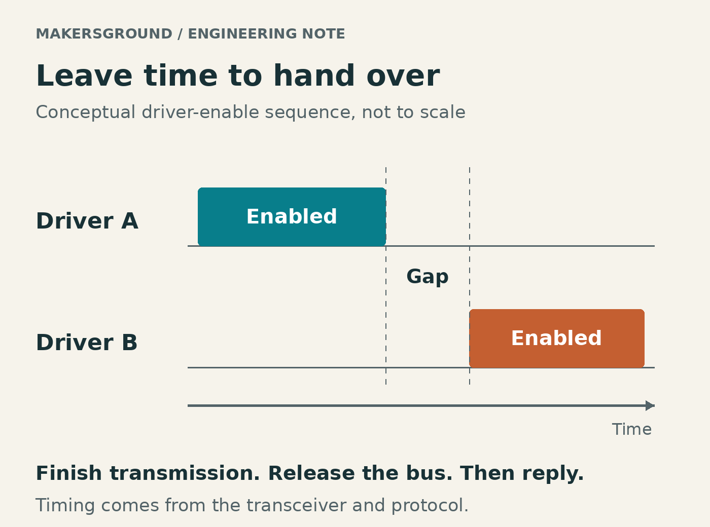
On a half-duplex bus, only one driver should be active at a time. Observe transmit data, driver enable and the differential bus together. Confirm that enable becomes effective before the first start bit, remains effective through the final stop bit, and releases the bus before the other node drives it.
Do not equate a completed software write, DMA transfer or empty transmit buffer with a completed frame on the wire. Check the UART’s documented completion event. For example, the TI TL16C752CI-Q1 datasheet distinguishes an empty transmit holding register from both the holding and shift registers being empty. The distinction matters when choosing the event that releases driver enable.
Include the transceiver’s maximum enable and disable delays under the applicable conditions, receiver-enable behavior and the protocol’s permitted reply timing. Hardware-assisted direction control still needs verification. Microchip’s PIC32CZ CA80/CA90 example holds transmit enable through the stop bits and an optional guard interval. That is a device feature, not a universal delay to copy.
Capture the shortest permitted reply as well as a longer exchange. An oversized delay may prevent overlap while still making the interface miss the start of a valid response.
A hypothetical three-node bring-up
Consider a bench controller and two remote measurement boards on one trunk. This is an illustrative setup, not a MakersGround customer system or reported test result.
First, inspect the unpowered harness and document termination and bias settings. Then power the reviewed configuration, leave all drivers released and measure idle behavior and input voltages at each receiver. Next, transmit a known pattern from one node at a time, checking the waveform at the receiving locations rather than only beside the source.
Finally, exercise request and reply traffic while capturing driver handover. If the first reply byte is missing, compare enable timing with the bus trace before changing the application timeout. If corruption appears only after adding a board, inspect its branch, termination, bias and loading before attributing the failure to its address. These observations narrow the investigation; they do not identify a root cause by themselves.
Keep the evidence with the prototype
Retain the cable map, board and firmware revisions, component documents, switch settings, measurement setup, waveform captures and error logs. State the tested cable lengths, node count, operating conditions and unresolved cases. Repeat the affected checks after a transceiver, harness or timing change.
MakersGround’s historical Gomicron project record documents mechanical design, PCB electronics, firmware and control, slicing software, prototyping and manufacturing. That scope provides context for reviewing physical wiring and firmware together. It does not establish that Gomicron used RS-485 or any component or test method discussed here.
For a new electronics and firmware development project, ask for this electrical baseline alongside the working demonstration. It gives the next engineer a reproducible starting point when a communication fault appears.
Sources and scope
Primary technical sources and the public project record were checked on 26 October 2026. Manufacturer examples apply to their stated devices and conditions. The bring-up sequence and three-node scenario are original engineering recommendations, not measured product results.