


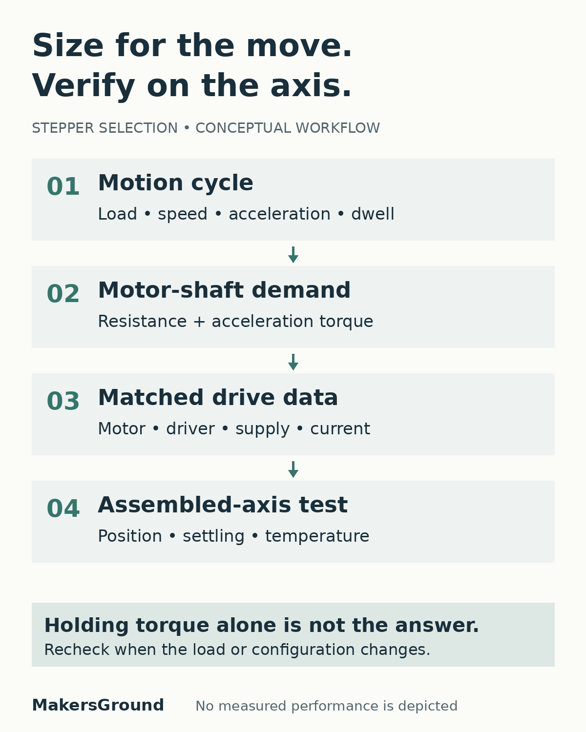
Size a stepper motor against the torque required throughout the axis’s speed and acceleration profile, using the selected motor and driver’s torque-speed data. Holding torque alone cannot show whether a moving axis will complete its job. The practical output is a matched motor, driver and mechanism specification, followed by a test on the assembled prototype.
For a founder commissioning a custom machine, the first useful question is not which motor frame fits the bracket. It is what the axis must move, how quickly it must move it, and what evidence will show that the choice is adequate. A larger motor can change the electrical, thermal and mechanical design without resolving an unclear motion requirement.
Start with the move the product needs
Describe one complete operating cycle before comparing catalog parts. Include the travel, payload range, direction, target speed, acceleration, dwell time and number of repeated moves. State how long the axis may take to settle before the next operation begins. A short positioning move may spend most of its time accelerating and decelerating rather than running at its nominal maximum speed.
Distinguish a requirement from an adjustable preference. If the process genuinely needs a particular cycle time, retain it as a constraint. If a demonstration simply used an aggressive acceleration setting, test whether a gentler profile would meet the actual need before redesigning the drive.
Prepare a compact input sheet:
- Moving mass and payload range, including cables or tooling that travel with the carriage.
- Transmission geometry, reduction ratio, friction estimates and orientation.
- Required motion profile, settling allowance and operating cycle.
- Available supply, driver constraints and expected ambient conditions.
- How actual position will be checked and what happens when the axis cannot complete a move.
MakersGround’s historical Gomicron engineering project documents mechanical design, custom electronics, firmware and control within one product. That is the relevant context for reviewing a motion axis across disciplines. The project record does not establish a particular stepper model, sizing calculation or measured motion result. This guide is general engineering guidance, not a reconstruction of that project’s drive system.
Convert the mechanism into motor-shaft demand
Keep the load calculation and the motor’s available torque separate. The mechanism imposes a demand; the motor and driver must meet it under stated conditions. Include resistance to steady motion and the additional torque needed to accelerate the translating load and rotating parts. Record whether each input is measured, supplied by a component manufacturer or estimated. Oriental Motor calculation guidance.
For a belt axis, pulley radius connects carriage force to shaft torque and linear speed to shaft speed. A screw axis uses its lead and efficiency instead. Do not transfer a belt calculation to a screw by changing only a dimension. Transmission losses, preload, seals and cable forces can matter, especially when the load estimate is otherwise small.
Use consistent units and refer every inertia to the same shaft. Check the motor rotor, pulleys, couplings and transmission as well as the payload. Reduction can change both reflected inertia and the motor speed needed for a given carriage speed. It is a design trade-off, not free torque. Oriental Motor inertia formulas.
A vertical axis also needs a separate assessment of gravity and load retention. An energized motor’s holding torque is not a substitute for a reviewed means of preventing a hazardous load movement after power loss. This article does not select protective equipment or establish machine safety.
Read the torque-speed curve with its test conditions
Holding torque describes a stationary energized condition. It is not the torque available at every running speed. Compare the calculated demand with the manufacturer’s applicable torque-speed curve, checking the motor winding, driver, supply voltage, current setting and connection configuration used to produce it. Oriental Motor specification definitions.
A part number without those conditions is an incomplete comparison. Two curves for the same motor can represent different drive arrangements. Preserve the actual document and revision in the selection record so that a later substitution does not inherit an unsupported performance assumption.
Review the entire intended move, including acceleration and the highest operating speed. Do not assume an axis can start instantly at its final running speed. Where the manufacturer distinguishes starting capability from running capability, use those definitions and an appropriate acceleration profile. Keep a documented allowance between demand and available torque, justified for the selected product and uncertain loads rather than copied as a universal multiplier.
Use inertia guidance as a product-specific check
The relationship between load inertia and motor rotor inertia helps frame the selection, but a single ratio is not a universal acceptance rule. Check current guidance for the selected motor family and control arrangement. A ratio that appears in an old tutorial should not overrule a newer manufacturer notice or the actual application’s settling requirements. Oriental Motor’s 2025 guidance update.
Keep the calculation transparent enough to revisit. If the team changes a pulley, screw, gearbox or payload, identify which speed, torque and inertia terms change. The review should lead to a revised motion specification, not simply an unchanged motor choice with a larger margin written beside it.
A hypothetical belt-axis review
Consider a hypothetical horizontal positioning axis moving a small inspection fixture. This is not a MakersGround customer system. The team has specified its travel and payload but has not yet selected a motor or driver.
First, convert the required carriage speed and acceleration into motor-shaft speed and acceleration using the proposed pulley geometry. Convert the resisting carriage force to shaft torque, then add acceleration torque for the translating load and rotating components, including the motor rotor. Keep the estimated friction contribution visible rather than hiding it inside an unexplained factor.
Next, compare that demand with a candidate motor-driver curve under the proposed electrical settings. If the operating point is unsuitable, the alternatives include changing the motion profile, transmission or drive combination. Compare those alternatives against the same cycle-time requirement. A slower acceleration that misses the required throughput is not an accepted solution; a bigger motor that overheats the enclosure is not one either.
Finally, reserve the selection decision until the assembled axis has been tested. The calculation narrows candidates and exposes assumptions. It does not prove that the prototype will reach and hold its commanded position under all intended conditions.
Check the driver and thermal duty together
A short movement duty cycle does not necessarily mean a cool motor. A stationary stepper can remain energized during dwell. Review running current, standstill-current behavior and the manufacturer’s limits for the motor and driver. Do not reduce current solely to lower temperature without checking whether the axis still meets its holding and motion requirements. ADI motor-manual example; TI stepper-loss guidance.
Specify the electrical configuration alongside the mechanical parts: driver model, supply range, current-setting convention, microstepping mode and any automatic current reduction. Distinguish peak and RMS current where the documentation does. An undocumented driver-setting change can invalidate the comparison that supported the original selection.
Test the representative repeated cycle in the intended enclosure and mounting arrangement. Record the operating conditions and temperatures against the relevant component limits. Our electronics enclosure thermal-validation guide explains how to keep the configuration and measurement locations clear. Do not present a brief open-bench movement as evidence of sustained thermal suitability.
Close the selection with an assembled-axis test
Agree the acceptance evidence before running the prototype. Check actual position through a suitable independent measurement or feedback method rather than treating the commanded step count as proof of motion. Use the intended payload range and representative cycle, including reversals, starts after dwell and the operating conditions that matter to the product.
Keep these records together:
- The mechanism revision and measured or estimated load inputs.
- The complete motor, driver, supply and firmware motion settings.
- The applicable torque-speed data and the demand calculation.
- Observed position and settling behavior across the agreed test conditions.
- Motor and driver thermal observations during the representative cycle.
- Remaining limitations, rejected configurations and the next release decision.
If the test fails, separate the symptoms before replacing parts. Position error, excessive settling, temperature and driver faults call for different investigations. Preserve the failed configuration and evidence so that the next run tests a specific change.
For a custom machine development review, ask for this selection record alongside the prototype. It turns “the motor seems strong enough” into a decision that the mechanical, electronics and firmware teams can inspect and maintain.
Sources
Primary manufacturer sources and the public project record were checked on 22 October 2026. The review workflow and belt-axis scenario are original recommendations and a hypothetical example, not measured project results. Component-specific documentation and the product’s risk assessment remain necessary.
- Oriental Motor: Stepper Motor Specifications.
- Oriental Motor: Motor Selection Calculation Formulas.
- Oriental Motor: Formula for Inertia.
- Analog Devices: QSH4218 Manual, v1.10, 24 April 2023.
- Texas Instruments: Stepper Motor System Power Loss Reduction Using Auto-Torque, January 2023.
- Oriental Motor: inertia-ratio guidance update, 18 March 2025.
- MakersGround: Gomicron DLP 3D Printer Engineering.