


A button that sometimes advances a menu twice has an engineering requirement hidden inside a usability complaint. The product must turn a physical action into one accepted state change, then turn that change into the intended application event. Those are separate steps, and each needs a test.
For a prototype review, we would ask for three things: the electrical input specification, the rule used to accept a new state, and evidence that the application responds correctly to both pressing and releasing the switch. A delay value alone does not describe the behaviour.
MakersGround’s Gomicron project documents work across mechanics, PCB electronics, firmware and control. Switch validation is a useful example of that hardware and firmware boundary. The checklist and timing example below are general engineering guidance, not a claim about Gomicron’s implementation or test results.
Define what counts as an action
Start with a plain-language acceptance requirement. For a menu button, it might be: one qualified press advances one item, holding the button does not advance again, and a qualified release makes the next press eligible. If holding should repeat, define its initial delay and repeat interval separately.
Before choosing a filter, write down:
- The shortest intentional press and release that the interface must recognise.
- The longest acceptable delay between an action and its visible response.
- Whether the application reacts on press, release, or both.
- What happens when the device powers up or wakes while the button is already held.
- Whether a disconnected cable or stuck input needs a fault indication.
Use requirements appropriate to the actual control. This article covers ordinary user-interface inputs. It is not a design or validation method for emergency stops, protective interlocks or other safety functions.
Keep the electrical signal, accepted state and event separate
Mechanical contacts can make and break repeatedly during a single action. Texas Instruments explains this mechanism in Debounce a Switch. Microchip’s switch-debounce exercise also notes that bounce can occur during release as well as press.
Review the input as three layers:
- Electrical input: the voltage at the receiving pin and whether it meets that device’s input requirements.
- Accepted state: the stable logical condition reported by the debounce mechanism.
- Application event: the action produced when an accepted transition occurs.
A clean accepted state can still create duplicate actions if application code treats every scan of a held state as a new press. Conversely, a correct event handler cannot repair a pin that is being driven outside its electrical limits.
Check the actual switch, pull resistor, input polarity, voltage levels, wiring and receiving device data sheet. If an RC network or Schmitt-trigger input is used, verify its thresholds and timing against that circuit, including component tolerances. Do not treat an added capacitor as evidence that the complete input has passed.
Choose an acceptance rule before choosing a number
Different debounce mechanisms have different behaviours. One design may wait for a candidate state to remain unchanged for a specified duration. Another may accept the first edge and ignore subsequent edges for a fixed interval. These are not interchangeable when a short pulse, a long burst of bounce or a rapid second action occurs.
Microchip’s AN1450 timing application note demonstrates device-specific delay and debounce arrangements. It is evidence that timing can be implemented in different ways, not a universal delay recommendation. Hardware filtering, a microcontroller peripheral and firmware can all be candidates; the selected method must meet the product’s requirements.
For a sampled stable-time method, describe the rule precisely: when the sampled input differs from the current candidate, start a new candidate interval; accept the candidate only after it has remained unchanged in the observations for the required duration. State the sampling interval and how elapsed time is measured. Sampling does not prove that the signal stayed unchanged between observations.
Avoid ambiguous descriptions such as “wait 20 samples” without a timing definition. Twenty observations at one-millisecond spacing span nineteen milliseconds from the first to the last. Also account for late task execution, interrupt loading and timer wraparound in the implementation review.
A hypothetical timing example
Assume an ordinary menu button is sampled every millisecond and the design requires 20 milliseconds of unchanged observations before accepting either state. These values illustrate the rule only; they are not measured switch characteristics or recommended defaults.
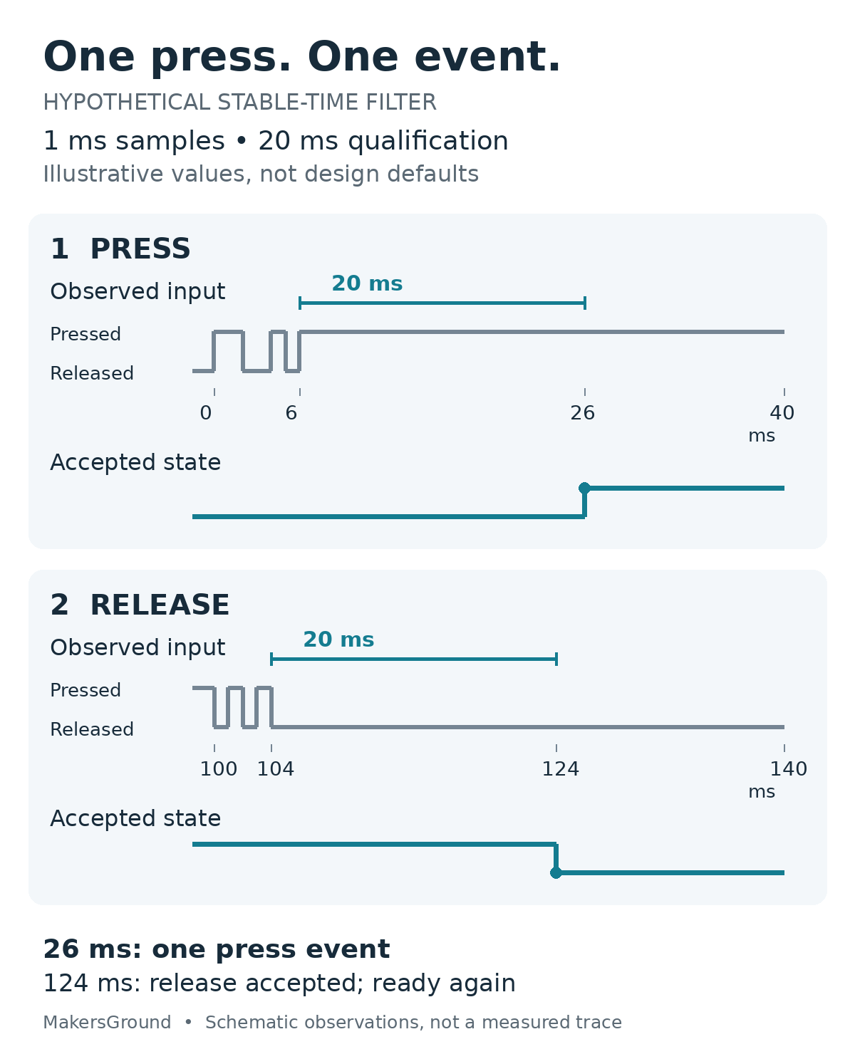
In this example, the observed input toggles during the initial press and becomes consistently pressed at 6 milliseconds. At 26 milliseconds, the elapsed stable interval reaches 20 milliseconds. The accepted state changes to pressed and the application emits one press event.
The button remains held. No further press events are generated. During release, observations toggle again and become consistently released at 104 milliseconds. The release is accepted at 124 milliseconds, which rearms the button for a later press.
The useful distinction is between the first edge and the last observed change. A stable-time filter starts its qualifying interval again when the candidate changes. If a deliberate press is shorter than the qualification interval, this example can reject it. The minimum valid action and maximum response delay therefore have to be considered together.
Test the complete path, including release
Capture the raw input, accepted state and application event together where practical. A scope or logic-analyser capture can show the electrical or digital input; a diagnostic output or timestamped record can expose the accepted transition and event. Record how instrumentation affects timing rather than assuming debug logging is invisible.
Normal actions and boundary cases
- Single press and release: check the event count and response delay over repeated actions, including gentle and quick operation.
- Long hold: confirm that a non-repeating control produces no additional press events.
- Two deliberate presses: verify both are recognised when the intervening release meets the specified minimum.
- Short disturbance: introduce a defined test stimulus and confirm the expected rejection or response. Record the stimulus rather than calling it “noise” without a description.
- Both edges: test release qualification explicitly. A release that is accepted too readily can rearm the control during bounce.
Product operating conditions
Repeat the relevant cases with the intended wiring and enclosure assembled, under representative processor activity, and across the supply and environmental conditions specified for the product. Include startup, reset and wake-up with the switch released and held. Check whether peripheral configuration or task scheduling changes in low-power modes.
Use several switches or assemblies when the validation plan calls for variation; one successful trace from one part is a debugging observation, not a population-level conclusion. If longer wiring introduces disturbances, investigate the electrical path instead of continually increasing the software delay.
Make a failure reproducible
A useful failure record says more than “double click happened.” Identify the board and harness revision, switch part, firmware build, input configuration, qualification rule and timing settings. Add the operating condition, stimulus, expected event count, observed count and a trace or timestamp record.
For example, a hypothetical failure might read: “Two application events during one held press; accepted state remained pressed throughout.” That points the next investigation toward event generation. If the accepted state briefly returned to released, the investigation instead includes qualification and the underlying input. The record narrows the question without pretending to prove the root cause.
Keep these decisions with the hardware and firmware interface specification. If a switch, pull resistor, input pin or timing rule changes, identify which cases must be repeated in the prototype revision test record.
What should leave the review
The deliverable is a small, explicit input contract: valid action timings, electrical assumptions, qualification behaviour, event rules and test evidence. It should be possible for another engineer to reproduce a press, understand when it becomes accepted, and explain why the application acts exactly once.
For founders reviewing a prototype, ask to see that chain rather than only a button demonstration. It connects the user’s action to a measurable engineering decision and makes the next hardware or firmware revision easier to assess.